
Display Panel and Display Device

a display panel and display device technology, applied in the field of display panels, can solve the problems of screw threads that cannot be fixed, etc., and achieve the effect of preventing the stress of tightening the screw that applies to the plastic frame, stable mounting, and preventing the breakage of screw threads

Inactive Publication Date: 2008-06-05
JAPAN DISPLAY CENTRAL CO LTD
View PDF2 Cites 8 Cited by
  • Summary
  • Abstract
  • Description
  • Claims
  • Application Information

AI Technical Summary

Benefits of technology

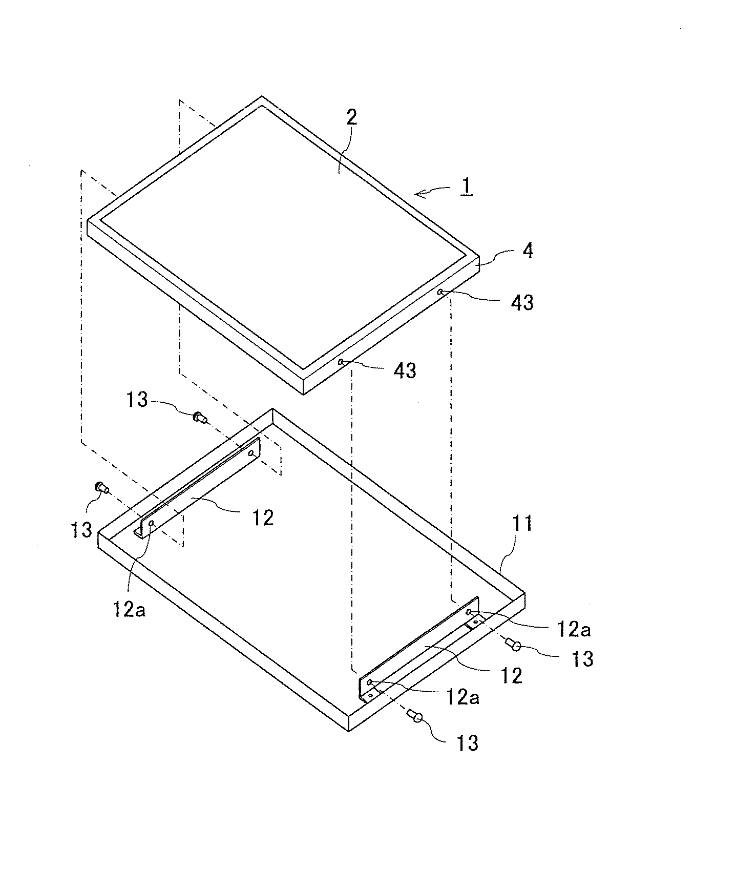
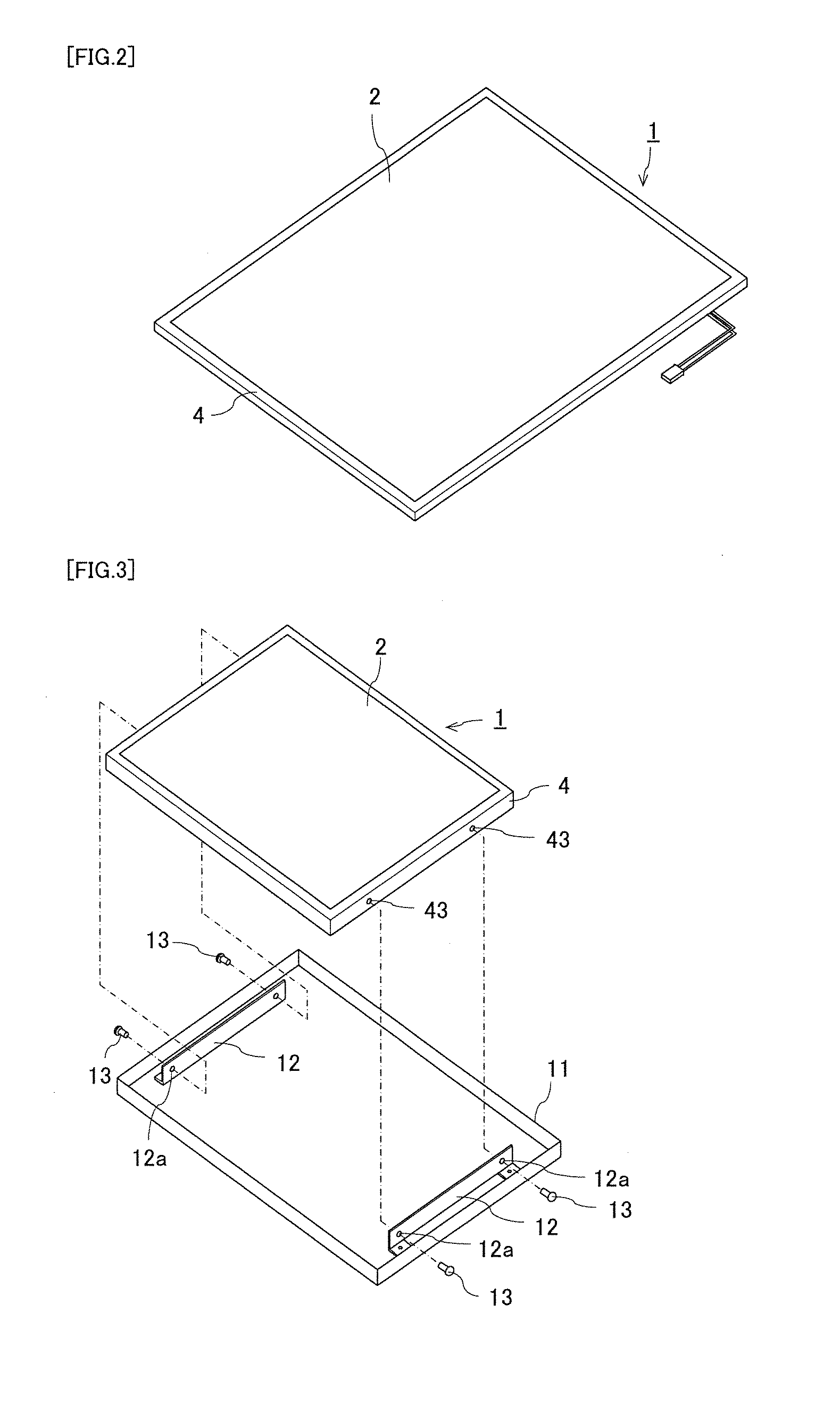
[0014]The display panel of this invention has formed a female screw adapted to fasten a fixing screw to a plastic frame. The plastic frame is thicker than the metallic frame and, therefore, allows a sufficient number of screw threads to be formed therein even when the metallic frame is thin. When the plastic frame is fastened to the display pane with screw, therefore, stable mounting is realized and consequently the screw thread is prevented from being broken when threads are repeatedly tightened at assembly and repairing processes.
[0015]Particularly the female screw is integrally formed inside the boss, the tubular projection stuck out from the plastic frame, and the tubular projection is supported with an elastic piece. In doing so, the stress of tightening the screw that applies to the plastic frame can be suppressed and it prevents adverse effects on the display such as the liquid crystal panel supported by the plastic frame. Tightening screws can be more smoothly.
[0016]This invention is capable of securing the number of screw threads allowed to be formed in the female screw while realizing manufacture of the display panel in decreased thickness and weight and enabling the display panel to be stably mounted on the outer cover on the display device without breaking screw threads. It is, therefore, capable of providing a display panel and a display device both with high quality.

Problems solved by technology

In this situation, an effort to thread on a metallic frame and use the screw threads as a female screw as contemplated by the invention disclosed in JP-A HEI 11-305209 results in failing to secure a sufficient number of screw threads and lacking in stable mounting.
Insufficient screw threads might cause screw threads to be broken, for example when threads are repeatedly tightened at assembly and repairing processes.
That contributes to quality problem.

Method used


Image

  • Display Panel and Display Device
  • Display Panel and Display Device
  • Display Panel and Display Device

Examples


Embodiment Construction

[0027]Now, the mode of embodying the display panel and the display device that are contemplated by this invention will be explained below by reference to the accompanying drawings.

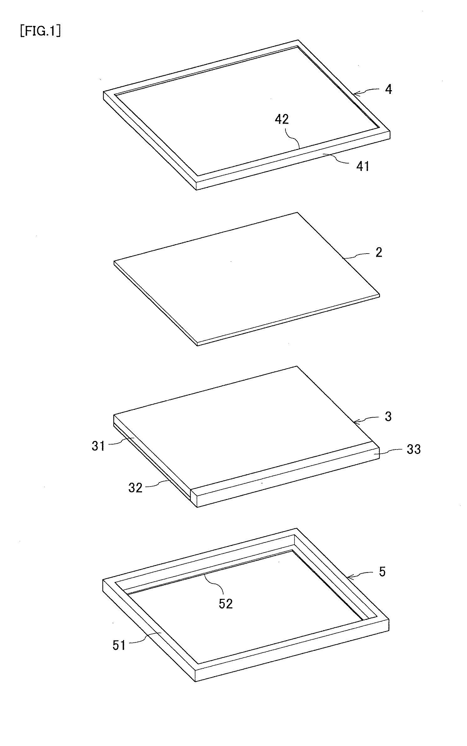
[0028]FIG. 1 is an exploded view illustrating a display panel 1 (liquid crystal display panel) assembled a surface light source in. The display panel in the present mode of embodiment is provided, as illustrated in FIG. 1, with a liquid crystal panel 2 and a light source panel 3 and is enabled to retain these panels by the combination of a metallic frame 4 and a plastic frame 5.

[0029]The liquid crystal panel 2 is built by having a liquid crystal material sealed in between an array substrate and a counter substrate. The array substrate has picture element electrodes and switching elements (thin-film transistors) formed in the shape of a matrix in conformity with display picture elements. On the array substrate, signal wires for sending electric signals to the picture element electrodes and signal wires for ...


PUM


Abstract

In a display panel mounted on a display device, a configuration of mounting that realizes decrease in thickness and weight and exhibits high reliability as well. The display panel is provided with a screen, a plastic frame supporting at least part of the outer periphery of a surface light source device, and a metallic frame disposed on the outside of the plastic frame. On the plastic frame, bosses for fixing the display panel are formed. The metallic frame is furnished at the positions opposite the bosses with holes that allow insertion of screws for fixing the display panel. The display panel is fixed to the outer cover of the display device by causing the fixing screws to be fastened by screwing into the bosses formed on the plastic frame of the display panel.

Description

BACKGROUND OF THE INVENTION[0001]1. Field of the Invention[0002]This invention relates to a display panel provided with a screen such as a liquid crystal panel and a display device provided with a display panel and, more particularly, relates to an improvement in the structure for attaching the display panel to the display device.[0003]2. Description of the Related Art[0004]In recent years, as display devices for information equipment including personal computers and word processors and for video and imaging equipment including televisions, camcorders, and car navigation systems, liquid crystal devices having features of lightweight, small thickness, and low power consumption have been widely used. These liquid crystal display devices, with a view to realizing a bright display screen, mostly adopt a configuration having built in a lighting unit (surface lighting source device) directed to projecting an illuminating light from behind a liquid crystal panel.[0005]The lighting units ar...

Claims


Application Information

Patent Timeline
Patent Type & Authority Applications(United States)
IPC IPC(8): F21V17/12
CPCG06F1/1637G06F1/1616
Inventor TAKUMA, MASAAKI
Owner JAPAN DISPLAY CENTRAL CO LTD
Learn More