
Anti-glare optical film and process for preparing the same

an optical film and anti-glare technology, applied in the field of optical films, can solve the problems of deteriorating the visibility of an image displaying device including a liquid crystal displaying device, high cost of former non-reflecting treatment, and inability to be said, so as to reduce the whitening of a screen, prevent glare, and reduce the effect of whitening

Inactive Publication Date: 2008-06-05
SUMITOMO CHEM CO LTD
View PDF10 Cites 19 Cited by
  • Summary
  • Abstract
  • Description
  • Claims
  • Application Information

AI Technical Summary

Benefits of technology

The film achieves reduced reflectivity and haze, improved clarity, and enhanced glare prevention without causing significant whitening, thereby maintaining high visibility and image quality on displays like liquid crystal display devices.

Problems solved by technology

Visibility of an image displaying device including a liquid crystal displaying device is remarkably deteriorated when the outdoor daylight is reflected on its image displaying surface.
The cost of former non-reflecting treatment is high due to necessity of formation of a multilayered film having a uniform optical film thickness.
In addition, in an even a method of obtaining anti-glare surface having no filler by a method of transferring a shape using a mat-like shaping film, since a reflected light distribution depends on a shape of a shaping film as a template, it can not be said that this method is not necessarily sufficient to prevent whitening.
However, as a method of forming irregularities on a shaping film, only a method of coating a composition composed of a filler and a binder resin on a substrate film to transfer the shape of the filler is disclosed and, since distribution of a filler and, consequently, arrangement of irregularities becomes random, it is thought that sufficient prevention of whitening can not be performed.
However, according to these formulations, a proportion of a flat surface of an anti-glare surface is increased at the same time, causing clarity of an image of the reflected on outdoor daylight, and anti-glare property is deteriorated.
However, the previously known glare preventing-treated film has not necessarily sufficient effect of preventing the aforementioned whitening, and it can not be said that sufficient visibility is obtained.

Method used


Image

  • Anti-glare optical film and process for preparing the same
  • Anti-glare optical film and process for preparing the same
  • Anti-glare optical film and process for preparing the same

Examples


example 1

[0098]A soda-lime glass having a thickness of 1.1 mm obtained from Nippon Sheet Glass Co., Ltd. was blast-treated with a mono disperse aluminum crystal “Sumicorundum AA-5” (average particle diameter: 5 μm) obtained from Sumitomo Chemical Co., Ltd. A blast pressure was 0.5 kg / cm2 (50 kPa), and a blast time was 120 seconds. Thus blast-treated glass was ultrasound-washed, dried, immersed in 10% by weight hydrofluoric acid at 40° C. for 1,200 seconds, sufficiently washed with pure water, and dried to prepare a template glass.

[0099]10 g of a urethaneacrylate ultraviolet curing resin “UA-1” obtained from Shin-Nakamura Chemical Co., Ltd., and 0.5 g of a photopolymerization initiator “Lucirin TPO” (chemical name: 2,4,6-trimethylbenzoyldiphenylphosphine oxide) obtained from BASF Corporation were dissolved in 10 g of ethyl acetate to prepare a coating solution. This coating solution was coated on one side of triacetylcellulose film having a thickness of 80 μm obtained from Fuji Photo Film Co....

example 2

[0103]According to the same manner as that of Example 1 except that a blast particle was changed to “Sumicorundum AA-18” (average particle diameter: 18 μm) obtained from Sumitomo Chemical Co., Ltd., a blast pressure was 0.4 kg / cm2 (40 kPa), and a blast time was 120 seconds, an anti-glare optical film was prepared. Results of optical property and visible assessment of the resulting film are shown in Table 1. It was found that this film also has sufficient anti-glare property and whitening preventing ability.

example 3

[0108]A borosilicate glass plate (trade name “Pyrex”; 5 cm square, 4 mm thickness; purchased by designating size and thickness) manufactured by Asahi Techno Glass Co., Ltd. was blast-treated using a zirconia bead (trade name “TZ-B53”, average particle diameter 53 μm, approximately monodisperse) manufactured by Tosoh Co., Ltd. An amount of a blast agent (zirconia bead) used was 100 ml, a blast pressure was 0.03 MPa, a distance from a blast nozzle to a glass plate was 40 cm, and a blast gun was fixed. Blast treatment was completed in about 5 minutes. A glass after blast treatment remained approximately transparent, but when observed with a reflection-type microscope manufactured by Keyence Corporation, it was confirmed that many fine cracks were produced on the surface at a depth of about 1 to 1.5 μm.

[0109]A glass after blast was immersed in an etching solution of weight ratio 5 / 1 / 1 / 10 of hydrogen fluoride (HF) / ammonium fluoride ((NH4)2 SO4) / sulfuric acid (H2SO4) / water at a temperatur...


PUM

PropertyMeasurementUnit
average particle diameteraaaaaaaaaa
average diameteraaaaaaaaaa
reflection clarityaaaaaaaaaa

Abstract

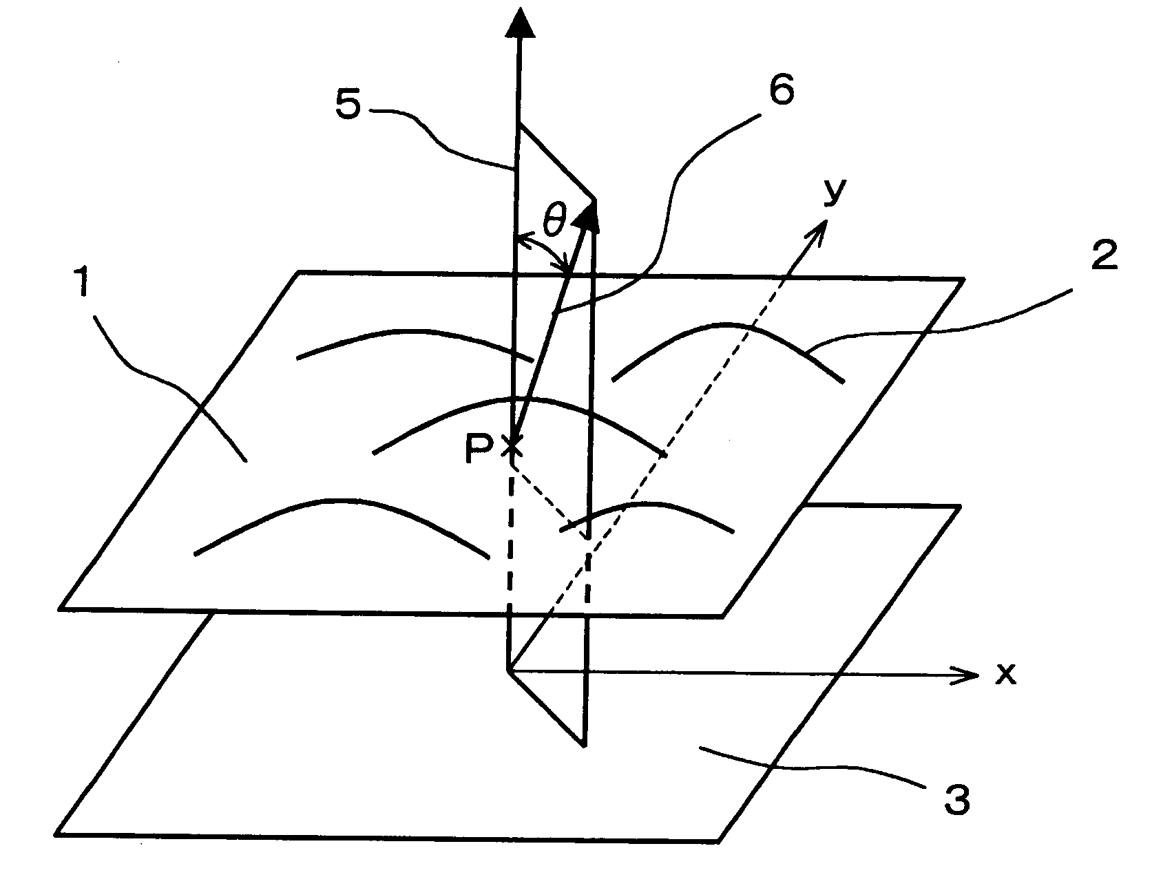
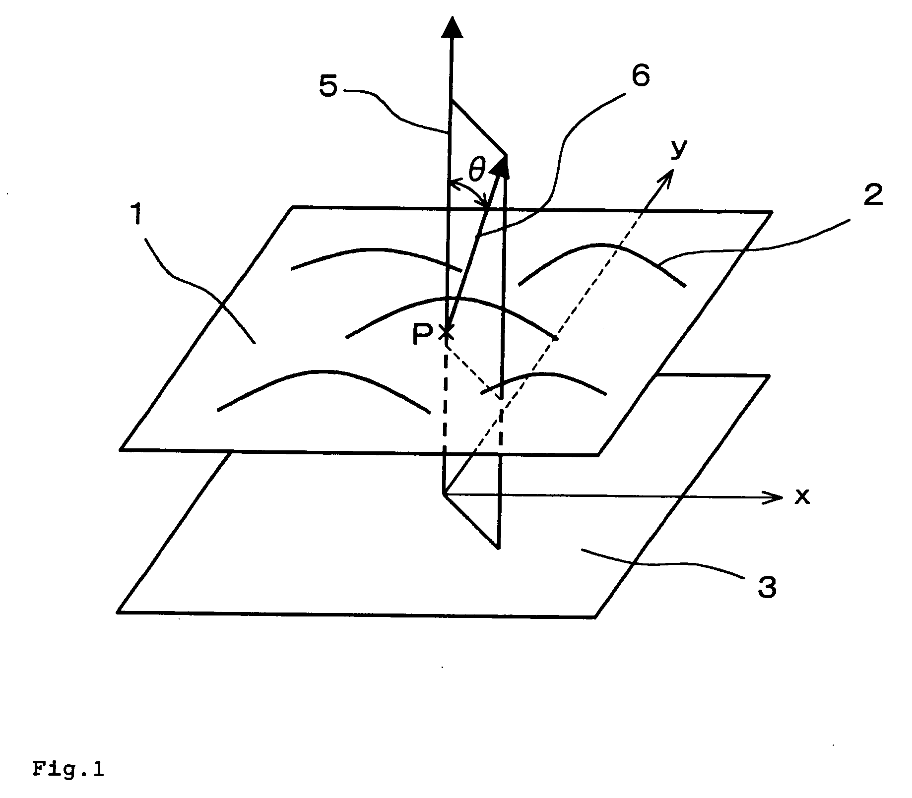
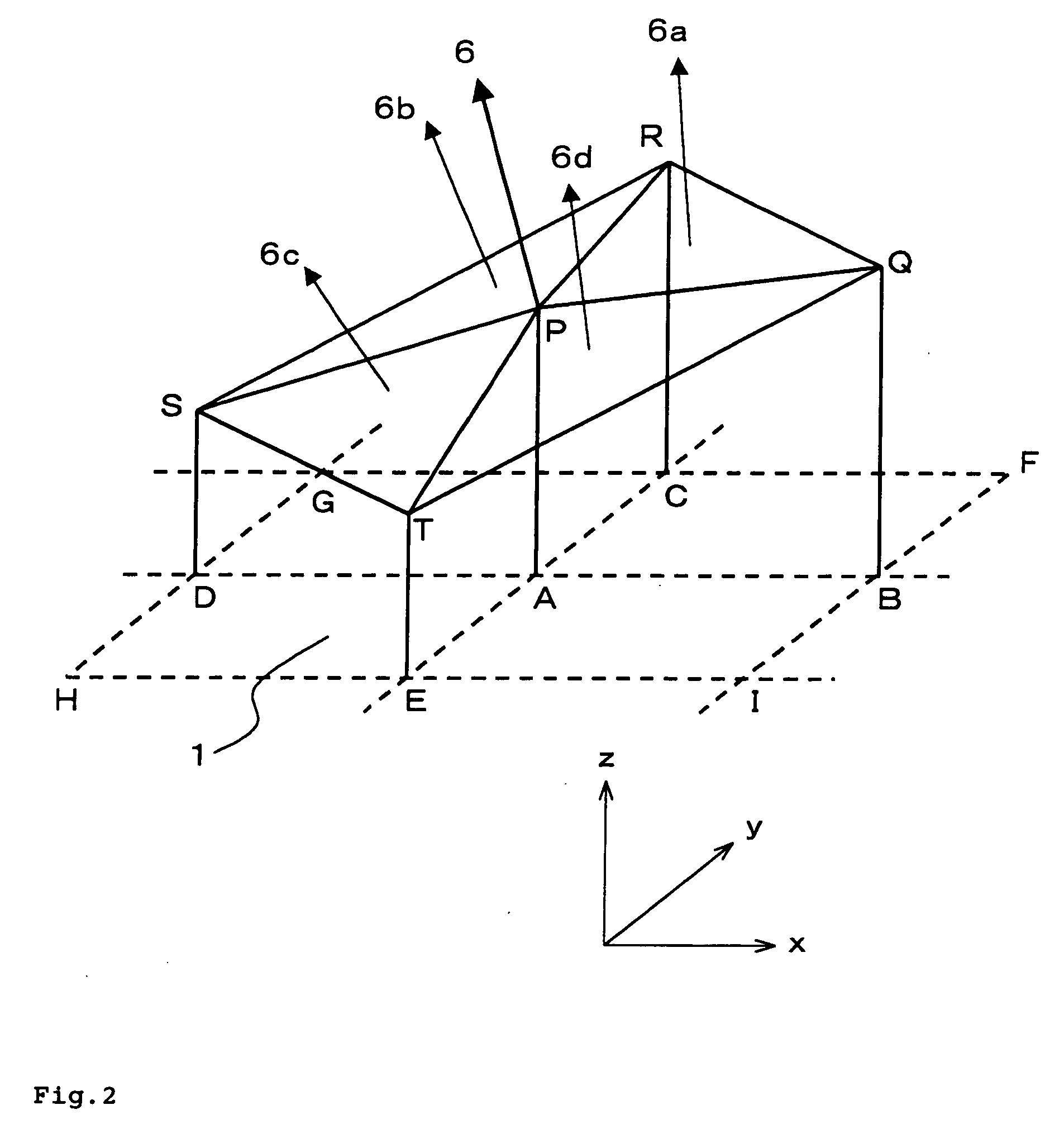
An anti-glare optical film which reduces in whitening of a screen without sacrificing anti-glare property, and a process for preparing the same. There is provided an anti-glare optical film has an irregular surface, wherein a ratio of areas of the surface having an inclination angle of 1° or less is 20% or less, a ratio of areas of the surface having an inclination angle of 5° or more is 20% or less, and a standard deviation of a height of the surface is 0.2 μm or less. There is also provided a process for preparing an anti-glare optical film.

Description

BACKGROUND OF THE INVENTION[0001]1. Field of the Invention[0002]The present invention relates to an optical film imparted property of preventing glare, which is used in a polarizing film of an image displaying device, and a process for preparing the same.[0003]2. Description of the Related Art[0004]Visibility of an image displaying device including a liquid crystal displaying device is remarkably deteriorated when the outdoor daylight is reflected on its image displaying surface. In utilities requiring high quality of image such as a television and a personal computer, utilities used in outdoor where the outdoor light is intense such as a video camera and a digital camera, and utilities which perform display utilizing the reflected light such as a reflecting-type liquid crystal displaying device such as a portable phone, the surface of a displaying device is generally treated for preventing the reflecting thereon. Reflecting on preventing treatment is roughly classified into non-ref...

Claims


Application Information

Patent Timeline
Patent Type & Authority Applications(United States)
IPC IPC(8): G02B27/00G02B1/11G02B5/02G02F1/1335
CPCG02B5/0221G02F1/133502G02B5/0268G02B5/0236G02B1/11G02B5/30
Inventor NAMIOKA, MAKOTOKUWABARA, MASATO
Owner SUMITOMO CHEM CO LTD
Learn More