
Damping ring for vibration isolation

a technology of vibration isolation and damping ring, which is applied in the direction of shock absorbers, machine supports, mechanical apparatuses, etc., can solve the problems of achieve the effect of reducing the stiffness of the damping ring, high stiffness, and poor cushioning and isolating performan

Inactive Publication Date: 2008-06-05
INVENTEC CORP
View PDF2 Cites 10 Cited by
  • Summary
  • Abstract
  • Description
  • Claims
  • Application Information

AI Technical Summary

Benefits of technology

[0008]Since there is no cushioning space between the current damping ring and the fixing member inserted therein, and the damping ring has the problem of having excessively high stiffness, the cushioning and isolating performance is poor. In view of this problem, the object of the present invention is to providing a damping ring, which is used for forming a gap between the damping ring and the fixing member inserted therein, and reducing the stiffness of the damping ring, so as to improve the damping effect and enhance the vibration isolating and cushion effect.
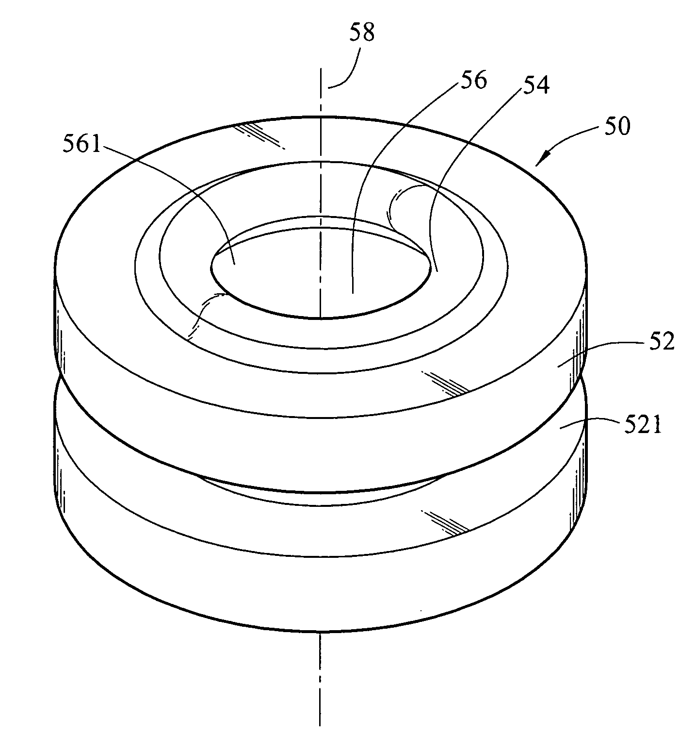
[0009]In order to achieve the above object, the present invention provides a damping ring, which is installed on a structure for a fixing member to be inserted therein, so as to fix the structure on a base via the fixing member, and the vibration transmission between the fixing member and the structure is isolated. The damping ring includes a body and a at least one protruding lip formed on the body, wherein the body is installed on the structure and has a through hole opened along the central axis of the body, and the through hole has two opening each respectively corresponding to each end surface of the body for the fixing member being inserted therein. The protruding lip is formed on the edge of at least one of the openings and surrounds the opening. The protruding lip extends outwardly along the central axis of the body, and extends inwardly along a radial direction of the body, so as to contact with the fixing member, such that a gap is formed between the fixing member and the body instead of directly contacting the fixing member with the body, thereby thus vibration transmitted between the fixing member and the structure is cushioned and isolated. Therefore, there is a larger space for relative displacement between the fixing member and the damping ring, and the distortion of the damping ring is increased during the vibration transmission, so as to produce a damping effect effectively to cushion and isolate the vibration.
[0010]In the present invention, the protruding lip and the gap can effectively reduce the radial stiffness and the axial stiffness of the damping ring. When the vibration occurs, the protruding lip makes the damping ring to have a large distortion, so as to improve the whole damping effect of the damping ring, and to disperse the vibration to other parts, thereby increasing the whole distortion of the damping ring, thus, the damping effect of the damping ring can be completely achieved to absorb the kinetic energy of the vibration. Meanwhile, a gap is also formed between the damping ring and the fixing member for producing a large relative displacement there-between, and the distortion of the damping ring is also enhanced, thus, the damping effect is effectively improved, and the buffering and isolating effect is enhanced.

Problems solved by technology

Since there is no cushioning space between the current damping ring and the fixing member inserted therein, and the damping ring has the problem of having excessively high stiffness, the cushioning and isolating performance is poor.

Method used


Image

  • Damping ring for vibration isolation
  • Damping ring for vibration isolation
  • Damping ring for vibration isolation

Examples


Embodiment Construction

[0021]The present invention is directed to preventing the structures such as the circuit board in the computer from being damaged due to the vibration produced by the vibration source, or due to the impact produced by moving or crashing the electronic device.

[0022]As shown in FIGS. 4 and 5, a damping ring 50 is disclosed in this embodiment installed on a structure 60 and for a fixing member 80 being inserted to fix the structure 60 on a base 70. The damping ring 50 includes a body 52 and protruding lips 54 formed on two end surfaces of the body 52.

[0023]The body 52 is cylinder-shaped and has a through hole 56 opened along the central axis 58 of the body 52. The through hole 56 has two opening 561 each respectively corresponding to each end surface of the body 52. The two end surfaces of the body 52 are respectively provided with a protruding lip 54 that is annular-shaped. Each protruding lips 54 is formed on the edge of the corresponding opening 561 and surrounds the edge of the ope...


PUM


Abstract

A damping ring is provided for isolating vibration between a fixing member and a structure. The damping ring includes a body and a protruding lip formed on the body. The body is installed on the structure and has a through hole opened along the central axis of the body, and the through hole is provided for the fixing member to be inserted therein. The protruding lip is formed on the edges of a opening of the through hole and surrounds the opening, and the protruding lip extends outwardly along the central axis of the body, and extends inwardly along the radial direction, so as to contact with the fixing member, such that a gap is formed between the fixing member and the body instead of directly contacting the fixing member with the body, thus vibration transmitted between the fixing member and the structure is cushioned and isolated.

Description

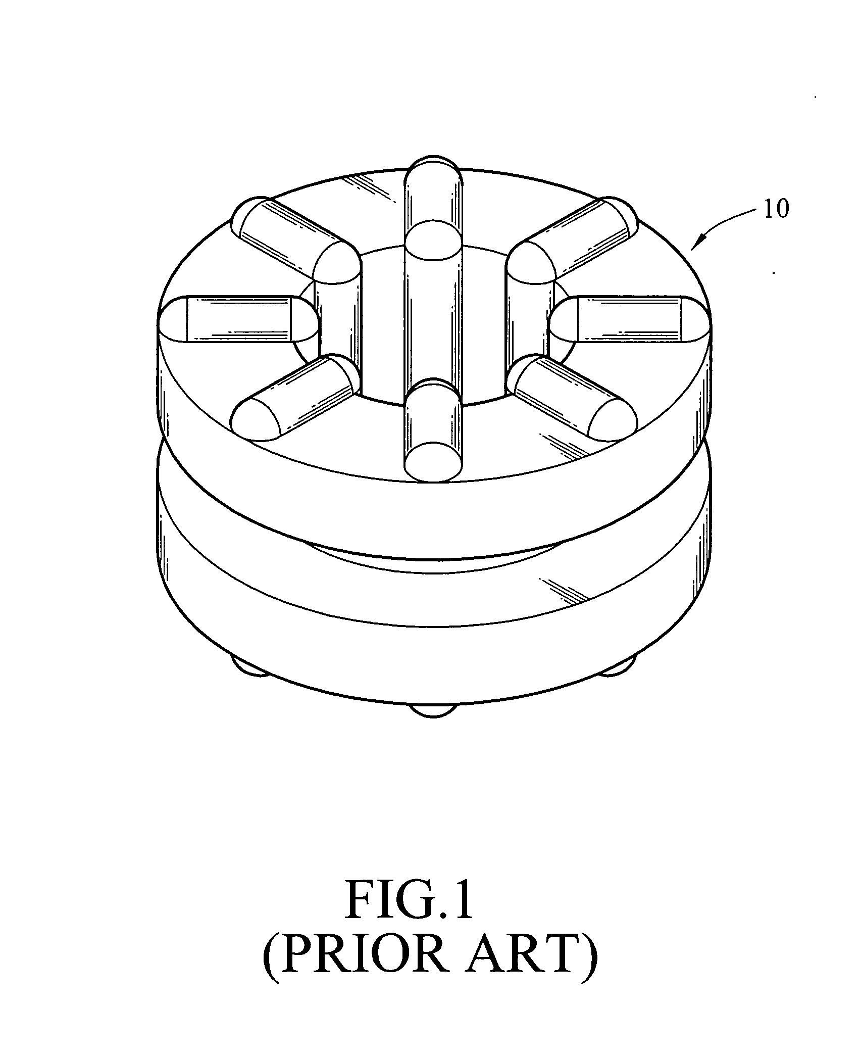
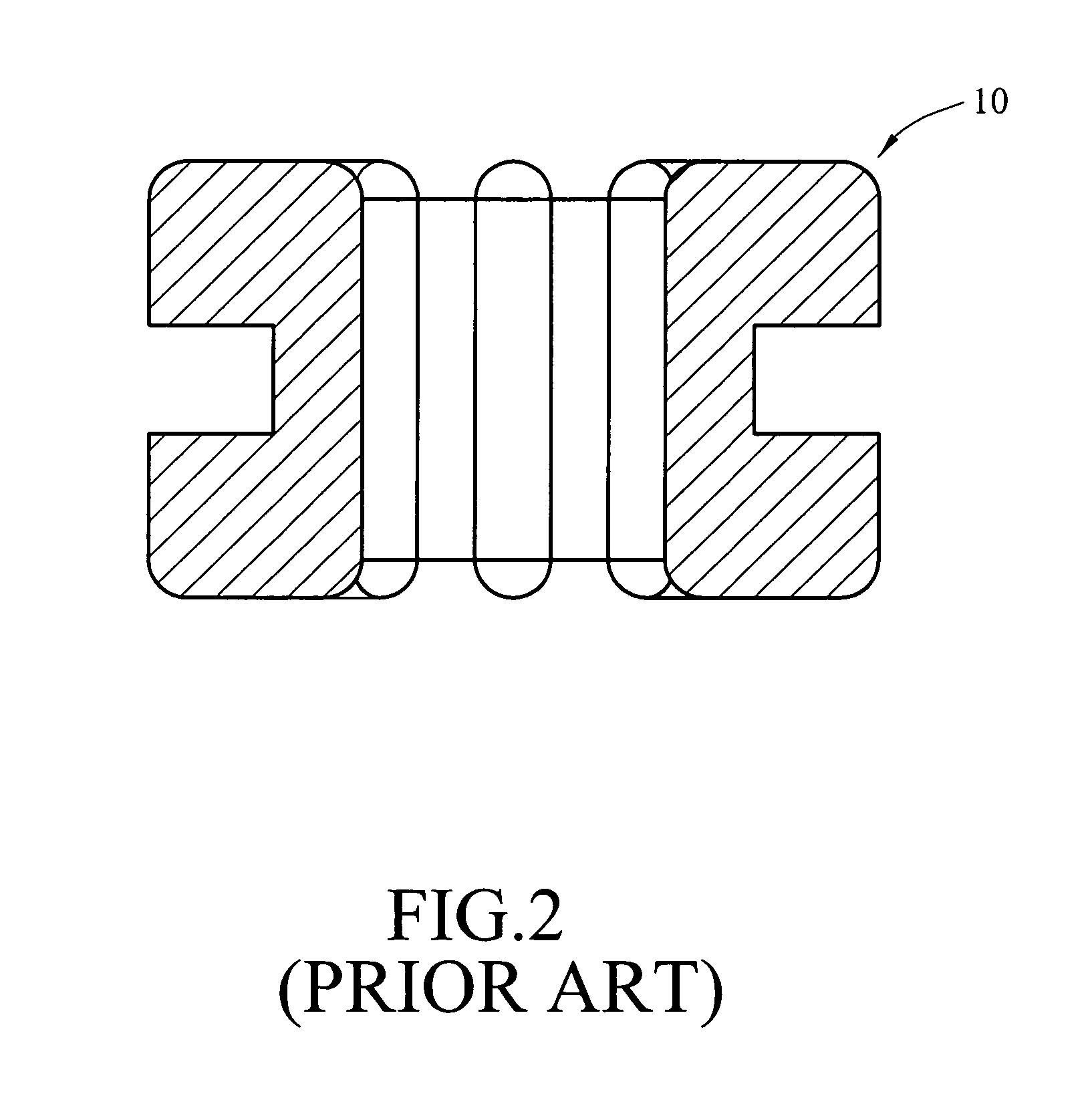
BACKGROUND OF THE INVENTION[0001]1. Field of Invention[0002]The present invention relates configuration of damping ring, and more particularly, to a damping ring for effectively isolating and cushioning the vibration.[0003]2. Related Art[0004]When a fan or a motor within the electronic device is running, the vibration generated by the fan or the motor is transmitted outwardly, which causes the structures in the computer, such as a circuit board, to vibrate and thus being damaged. Besides the vibration generated by the vibration sources such as the fan or the motor, when the electronic device is moved or crashed, the impact or vibration generated by an external force will also be transmitted to the structures.[0005]Referring to FIGS. 1, 2 and 3, in order to isolate and cushion the vibration, the currently used damping ring 10 for vibration isolation is installed in a fixing hole 12 formed on a structure 14, for a fixing member 18, such as a bolt, to pass through, being inserted in to...

Claims


Application Information

Patent Timeline
Patent Type & Authority Applications(United States)
IPC IPC(8): F16F7/104
CPCF16F1/3732
Inventor TSAI, HSIEH-LIANG
Owner INVENTEC CORP
Learn More