Low Torque Ball Valve With Dynamic Sealing

a ball valve and low-torque technology, applied in the field of ball valves, can solve the problems of low-torque ball valves, high dynamic friction, and high compression force against downstream seals, and achieve the effect of reducing torqu

Active Publication Date: 2008-06-05
TAC LLC A LIMITED LIABILITY COMPANY ORGANIZED & EXISTING UNDER THE LAWS OF DELAWARE
View PDF9 Cites 19 Cited by
  • Summary
  • Abstract
  • Description
  • Claims
  • Application Information

AI Technical Summary

Benefits of technology

[0014]Embodiments of invention provide an apparatus and method for reducing the torque required for repositioning a valve member of a ball valve, and to ball valves incorporating same.
[0016]In one embodiment of the present invention, to overcome the increased torque that results from the deformation and indentations in the downstream seal during various operating conditions as discussed above, a resilient, shaped member is utilized behind the downstream seal to provide a substantially uniform counter force across the sealing face of the downstream seal. In one embodiment a shaped rubber member providing a contact surface along substantially all of the back of the sealing face of the downstream seal is provided to minimize the downstream seal deformation and indentations that result in prior ball valve downstream seal designs. In an alternate embodiment, this same shaped back member may be used to provide the same substantially uniform back or counter force along substantially the entire sealing face of the upstream seal as well. In one embodiment the sealing member is Teflon and the shaped sealing back member is rubber.
[0017]In one embodiment to the present invention, the upstream seal for the ball valve provides dynamic sealing against the valve member. This is accomplished in one embodiment by providing a spring force to bias the sealing member against the valve member, while allowing for a variable sealing force thereagainst under different operating pressures. To ensure that the upstream sealing member maintains the seal under higher fluid pressure conditions, the upstream sealing member includes a ramped surface and an o-ring behind the sealing face of the upstream seal member. The upstream seal member is configured to allow the o-ring to be in fluid communication with the inlet pressure of the valve. As the inlet pressure increases, the o-ring is biased toward the valve member and, acting on the ramped surface of the upstream seal member, results in a dynamic increase in sealing pressure under increased fluid pressure conditions. As the inlet pressure decreases, the o-ring is allowed to move along the ramped surface away from the valve member. This reduces the pressure of the seal on the valve member, thereby allowing for a reduced torque to rotate the valve member.

Problems solved by technology

This is because typical valve products rely on manufacturing processes that are imperfect.
Variances in machining the valve, for example, can cause valves to have extremely high torques after assembly or low torques after assembly.
This results in a high compression force against the downstream seal, which creates high dynamic friction between the downstream seal and the valve member, and also generates significant elastic deformation of the relatively soft material of the downstream seal.
The high dynamic friction created by this inherent characteristic of prior traditional ball valves results in the actuator having to generate high rotational torque to rotate the ball through the 13 degrees just after the valve closes, or the 13 degrees of rotation just before the valve opens.
Additionally, when the valve member is partially open the edge of the throughbore will press into the downstream seal at two positions, resulting in a deformation or indentation along these two contact areas.
These indentations or deformations also substantially increase the torque required to reposition the valve member.
In addition, when the valve is closed, and stays closed while exposed to high close-off fluid pressure for the long period time, the high close-off pressure fluid pushes the valve member constantly against the downstream seal.
This results in a high compression force that creates a high static friction between the downstream seal and the valve member, and also causes significant deformation of the soft material used for the seal, due to the low compressive strength of such seal materials.
These conditions individually and in combination significantly increase static and dynamic friction between the seals and the valve member, requiring that the actuator generate an undesirably high breakaway torque to break loose and reposition the valve member.
This has required that the actuators in prior ball valves be physically larger and heavier, more costly, and consume more power during operation than would be the case if the inherently high torques encountered in prior ball valves could be reduced, especially under the operating conditions described above.

Method used


Image

  • Low Torque Ball Valve With Dynamic Sealing
  • Low Torque Ball Valve With Dynamic Sealing

Examples


Embodiment Construction

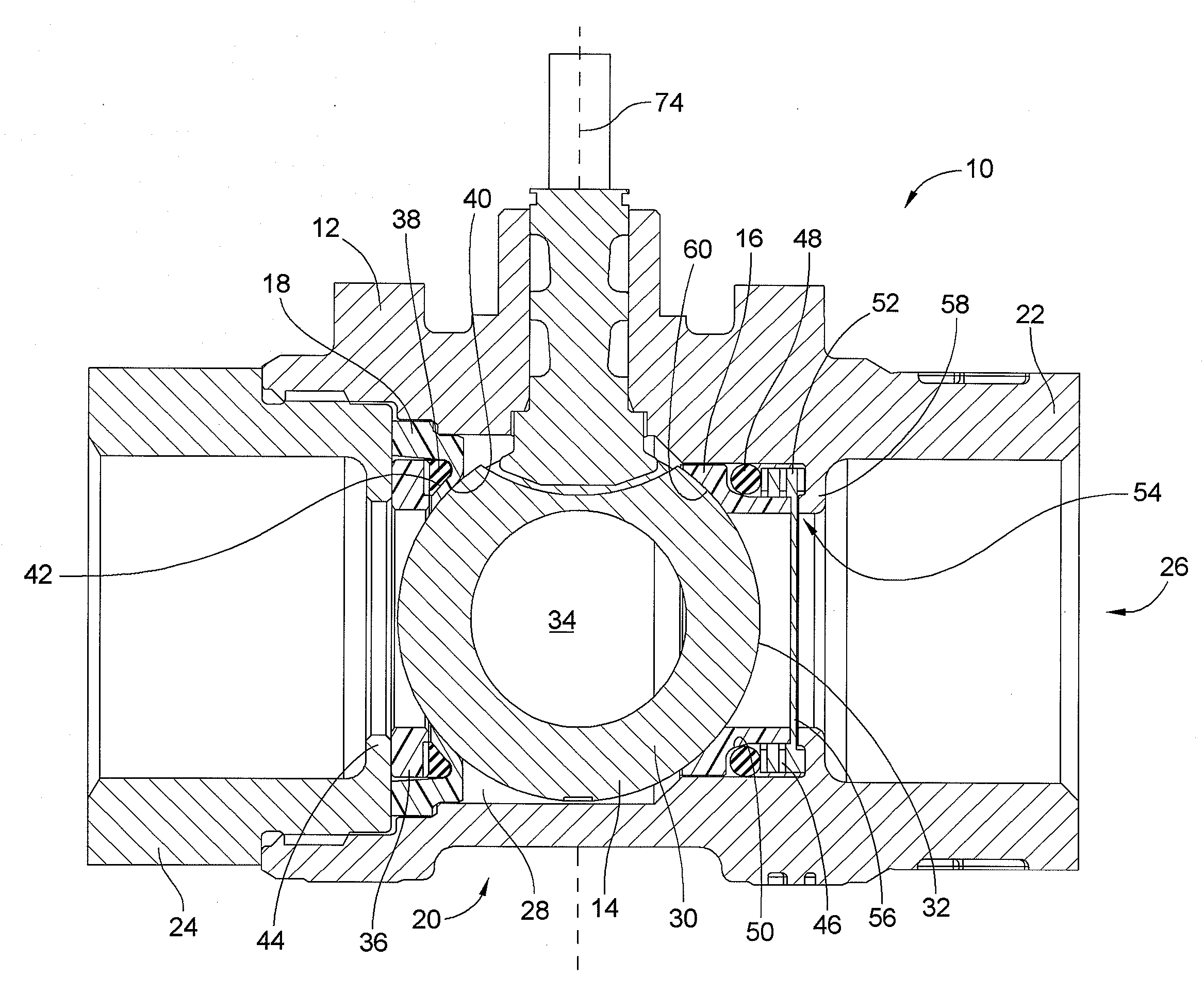
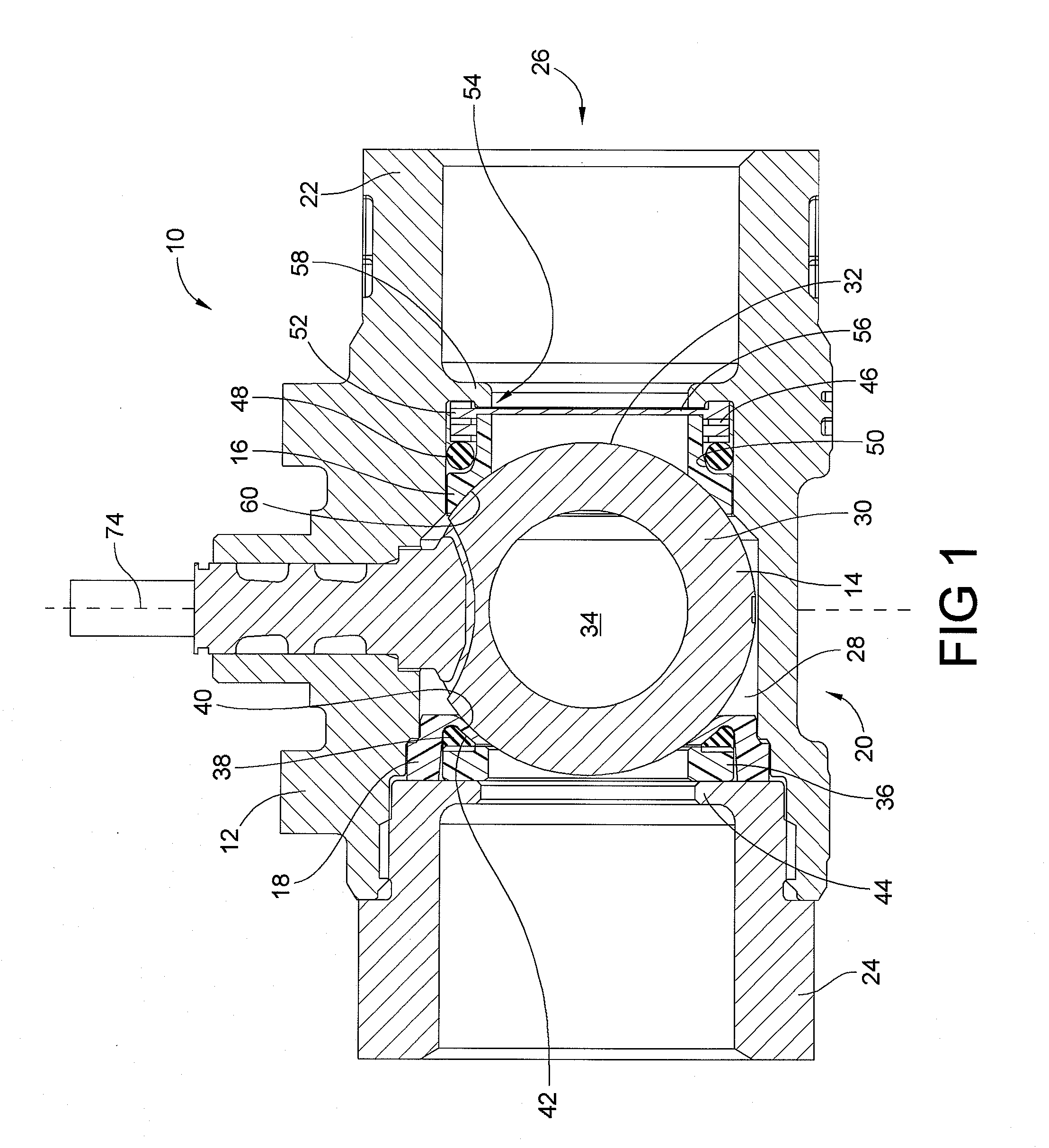
[0022]FIG. 1 shows a first exemplary embodiment of a ball valve 10, according to the invention. The ball valve 10 includes a valve body 12, and a valve member 14 operatively connected to the valve body 12 by an upstream and a downstream seal 16, 18.

[0023]The valve body 12 includes a central section 20, an upstream flow-through end 22, and a downstream flow-through end 24. The upstream and downstream flow-through ends 22, 24 are threadably joined to the central section 20, to form the valve body 12, and defines a flow passage 26 having an inlet formed by the upstream flow-through end 22, an outlet formed by the downstream flow-through end 24, and a valve receiving chamber 28 disposed between the upstream and downstream flow-through ends 22, 24.

[0024]The valve member 14 of the exemplary embodiment has an outer wall 30 defining a generally spherical shaped outer surface 32, and includes a throughbore 34 therein. The valve member 14 is disposed within the valve receiving chamber 28 of t...


PUM


Abstract

A ball valve having reduced torque requirements for rotation is presented. Torque reduction is realized by providing a shaped sealing back member to provide a back force behind essentially the entire sealing surface of the downstream seal. Torque reduction is also realized by providing a dynamic sealing configuration that varies the sealing force over the valve's operating pressure conditions. An initial bias sealing force is applied by a spring member which also provides a low uniform as-assembled valve torque. As fluid pressure increases, the sealing pressure also increases as an o-ring is forced along a ramped surface of the seal. As inlet pressure decreases, the o-ring is allowed to back down the ramped surface to reduce the sealing force against the valve member. This sealing configuration allows for reverse flow or improper installation of the ball valve, and bottoms out to maintain a sealing force at higher back pressure conditions.

Description

FIELD OF THE INVENTION[0001]This invention relates to ball valves, and more particularly to an apparatus and method for dynamically sealing the valve member of a ball valve to allow for a reduction of the torque required for turning the valve member of such a ball valve.BACKGROUND OF THE INVENTION[0002]It is generally advantageous to reduce the torque required for repositioning the valve member in a ball valve. This is especially true for ball valves having an actuator motor connected to the valve member for repositioning the valve member, because lowering the torque requirement will allow a smaller actuator to be utilized. Generally speaking, smaller actuators can be produced at lower cost than larger actuators, and require less input power, thereby reducing both the initial cost and the operating cost of the actuator.[0003]Typical ball valves have a valve body and a valve member operatively connected to the valve body by an upstream and a downstream seal. The valve body defines a ...

Claims


Application Information

Patent Timeline
IPC IPC(8): F16K5/06
CPCF16K5/0642F16K5/205F16K5/0678
Inventor THOMAS, KURT R.JORNOD, EUGENE R.
Owner TAC LLC A LIMITED LIABILITY COMPANY ORGANIZED & EXISTING UNDER THE LAWS OF DELAWARE
Why Eureka
Try Eureka