
Overhead traveling and transporting apparatus

a technology for transporting equipment and traveling, applied in the direction of runways, safety gear, load-engaging elements, etc., can solve the problems of increasing cost and complicated structure of transporting carriages

Inactive Publication Date: 2008-06-05
ASYST TECHNOLOGIES JAPAN INC
View PDF3 Cites 21 Cited by
  • Summary
  • Abstract
  • Description
  • Claims
  • Application Information

AI Technical Summary

Benefits of technology

[0007]It is therefore an object of the present invention to provide an overhead traveling and transporting apparatus, which can detect an obstacle forward in the traveling direction of the transporting carriage and an obstacle downward from the transporting carriage at relatively low cost.
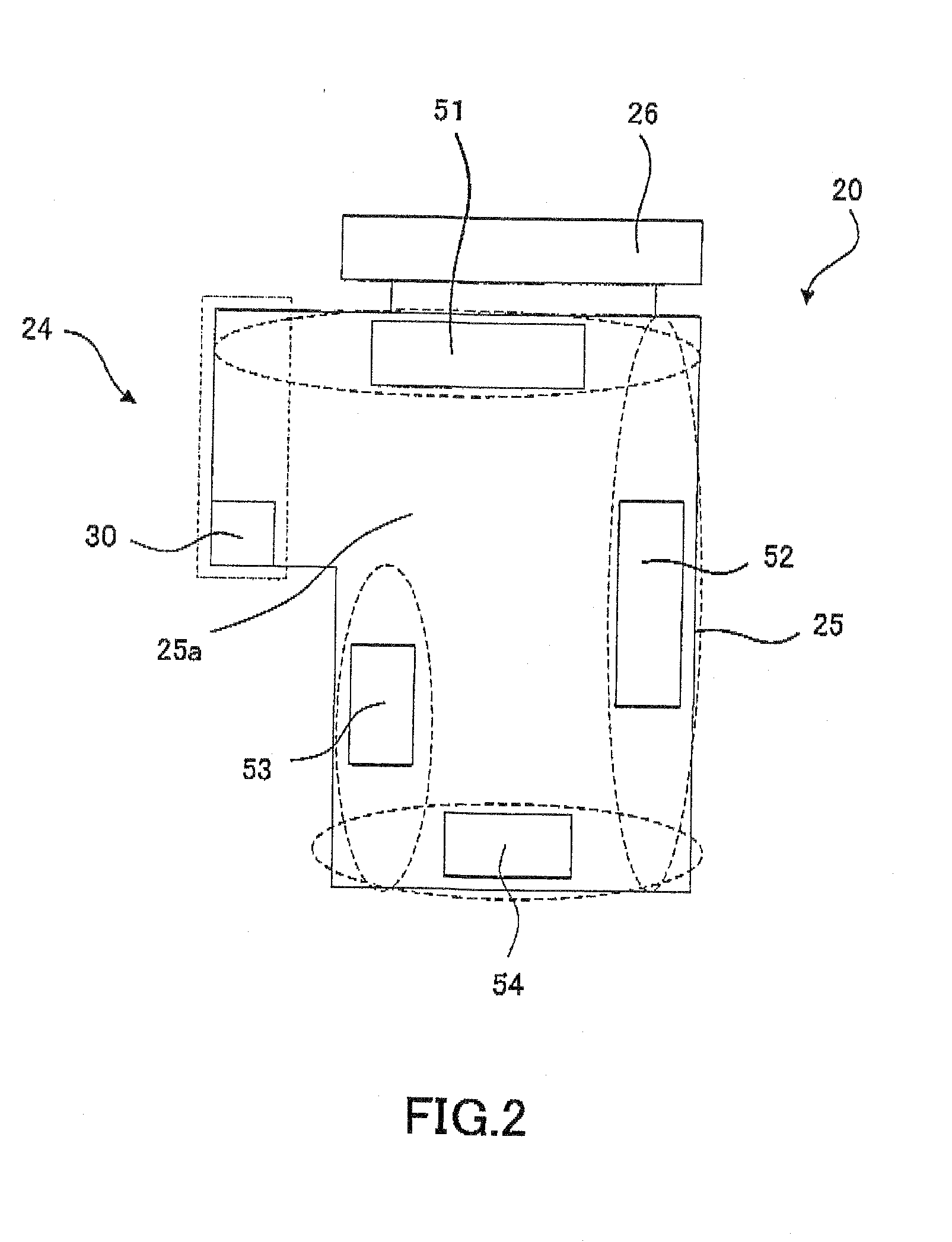
[0009]According to the present invention, the selecting device controls the sensor as following. Namely, in case that the transporting carriage is traveling, the light beam is emitted forward in the traveling direction of the transporting carriage. In case that the gripping mechanism is moved down, the light beam is emitted downward from the transporting carriage. In either case, the monitoring device monitors in the direction of emission. Alternatively, the light beam of the sensor is consistently emitted in directions including the forward traveling direction of the transporting carriage and the downward from the transporting carriage (wherein the direction of emission of the light beam may be sequentially switched over). In this occasion, the selecting device controls the monitoring device to (i) monitor in the direction of emission of the light beam which is emitted forward in the traveling direction of the transporting carriage, in case that the transporting carriage is traveling, and (ii) monitor in the direction of emission of the light beam which is emitted downward from the transporting carriage, in case that the gripping mechanism is moved down. Accordingly, by virtue of just one sensor, the detection of an obstacle possibly existing forward in the traveling direction can be performed when the transporting carriage is traveling, and the detection of an obstacle possibly existing downward from the transporting carriage can be performed when the gripping mechanism is moved down. Therefore, it is possible to realize the detection of an obstacle forward in the traveling direction and the detection of an obstacle downward from the transporting carriage at low cost.
[0011]According to this aspect, it is possible to realize both of the monitoring forward in the traveling direction and the monitoring downward, without the necessity of changing the direction of emission of the light beam.
[0015]By constructing in this manner, the obstacle possibly existing on the opposite side (e.g., the near side in the embodiment) of the path of the gripping mechanism can be certainly monitored. Especially, it is possible to avoid the gripping mechanism or the FOUP itself from being detected as the obstacle in the downward monitoring areas even if the downward monitoring is continued during the downward movement of the gripping mechanism. In other ward, it is possible to perform the downward monitoring not only before the movement but also during the movement of the gripping mechanism moved down. Further, the downward monitoring area can be substantially minimized and the downward monitoring can be simply and easily performed since the whole area where the gripping mechanism passes through is not required to be monitored.
[0019]By constructing in this manner, it is possible to avoid an object for detection from being erroneously detected as the obstacle, which exists out of the path of the transporting carriage when the transporting carriage is traveling.
[0021]By constructing in this manner, it is possible to avoid an object for detection from being erroneously detected as the obstacle, which exists out of the path of the gripping mechanism when the gripping mechanism is moved down.

Problems solved by technology

Thus, there arises such a problem that the structure of the transporting carriage becomes complicated and the cost is increased.

Method used


Image

  • Overhead traveling and transporting apparatus
  • Overhead traveling and transporting apparatus
  • Overhead traveling and transporting apparatus

Examples


Embodiment Construction

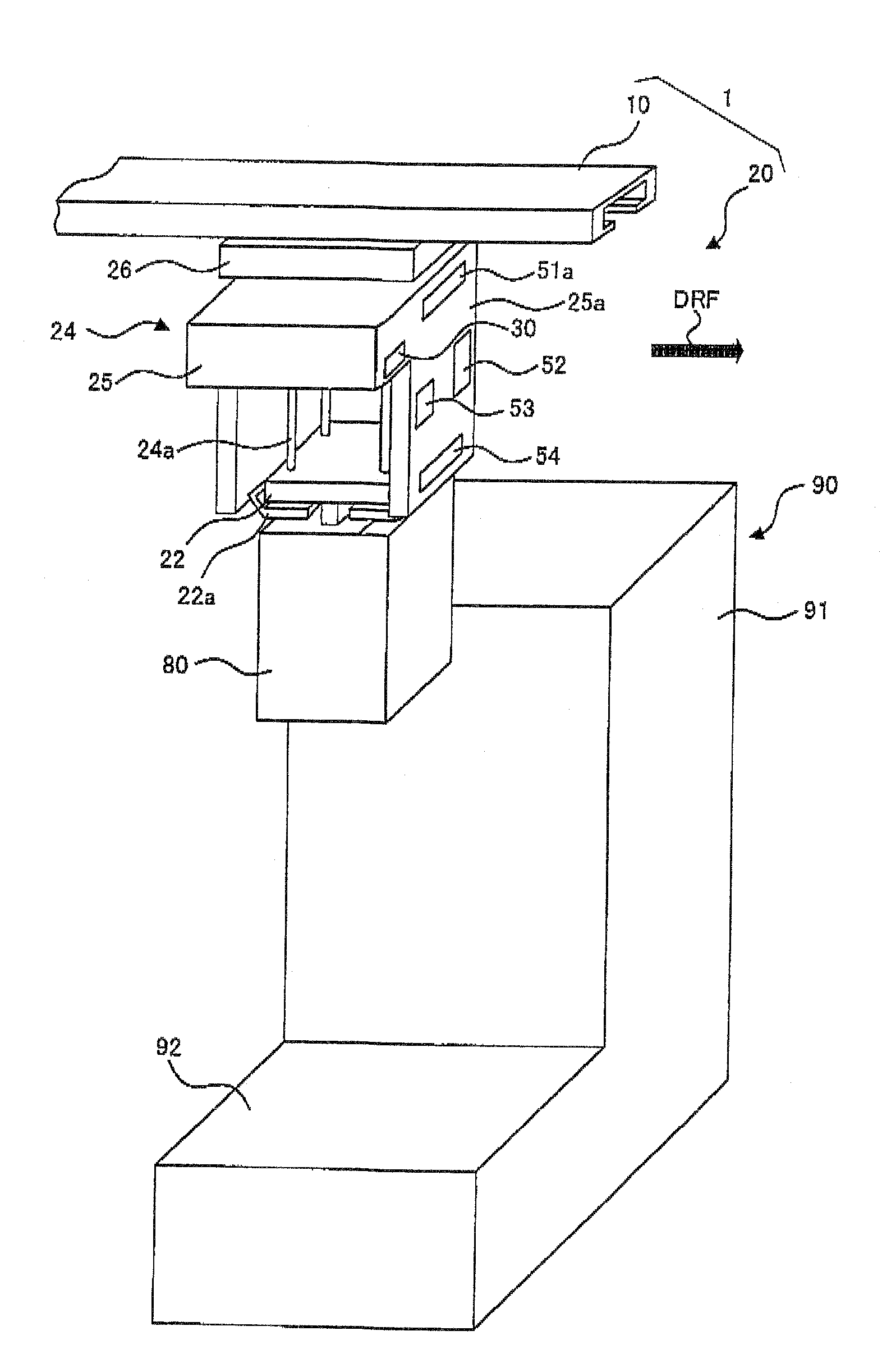
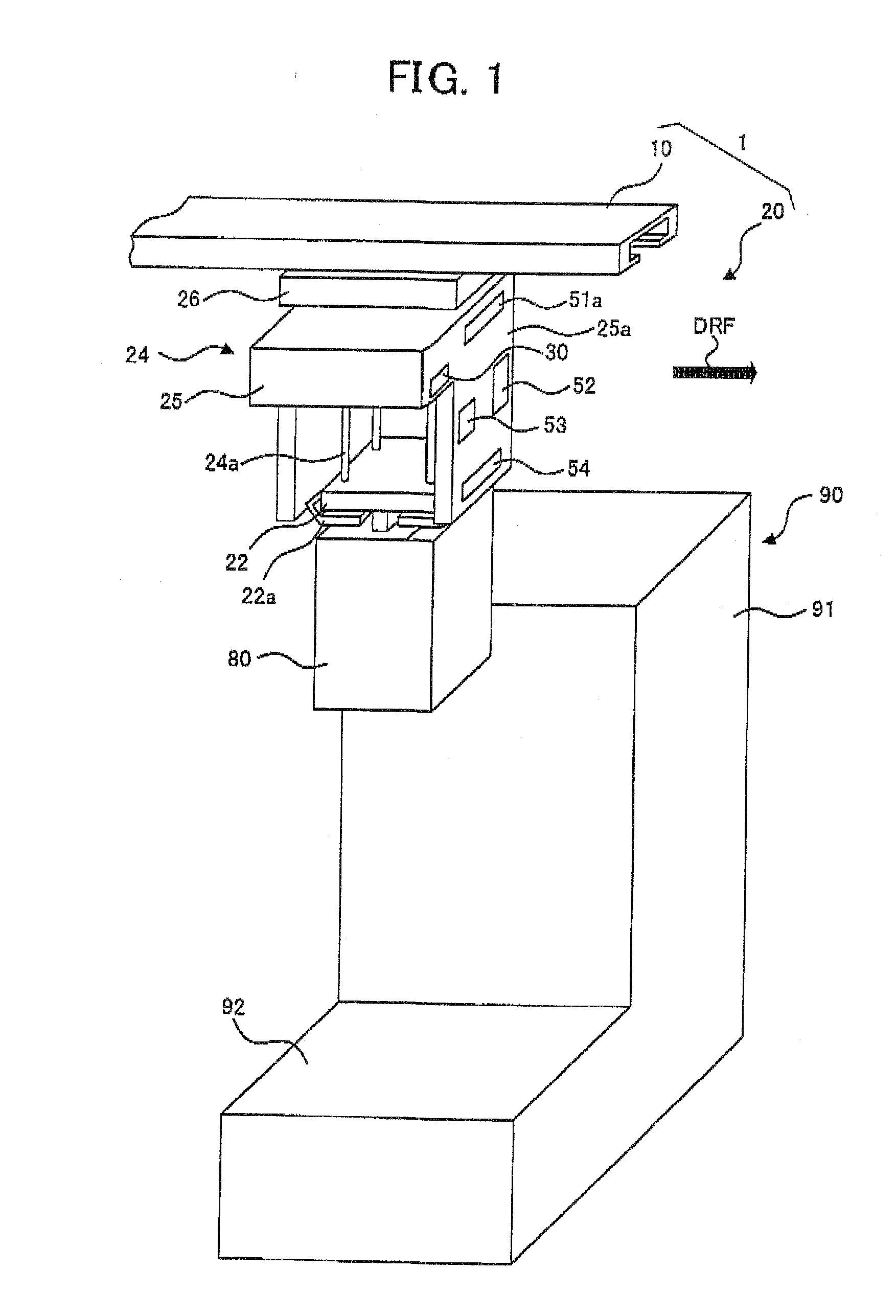
[0028]Referring to the accompanying drawings, an embodiment of the present invention will be now explained FIG. 1 shows an overall structure of an OHT (Overhead Hoist Transport) system 1, as one example of the overhead traveling and transporting apparatus of the embodiment of the present invention.

[0029]As shown in FIG. 1, the OHT system 1 is a transporting system or apparatus for transporting a FOUP 80 in which semiconductor wafers are contained, in a manufacturing facility for a semiconductor device. The OHT system 1 is provided with: a track 10 which is installed on or beneath the ceiling of the manufacturing facility; and a transporting carriage 20 which travels while holding the FOUP 80 in such a manner that the transporting carriage 20 is suspended and guided by the track 10 in a suspended condition. Nearly beneath the track 10, a main body 91 of a semiconductor manufacturing apparatus 90 among a plurality of semiconductor manufacturing apparatuses (e.g., wafer processing appa...


PUM


Abstract

An overhead traveling and transporting system includes a transporting carriage traveling along a track. The carriage has a gripping mechanism to grip an object, a hoisting mechanism to move down the gripping mechanism to a load port for the object, and a sensor emitting a light beam within a pseudo plane surface and receiving a reflection thereof. The system also has: a device for monitoring an obstacle existing in an emission direction of the emitted light beam, based on the reflected light; and a selecting device for establishing one condition that the obstacle existing forward in the traveling direction is monitored if the transporting carriage is traveling and establishing another condition that the obstacle existing downward from the transporting carriage is monitored if the gripping mechanism is moved down, by selecting the direction of emission and / or selecting an area of monitoring by the monitoring device.

Description

BACKGROUND OF THE INVENTION[0001]1. Field of the Invention[0002]The present invention relates to an overhead traveling and transporting apparatus for holding a transported object in such a manner that the apparatus can move up and down the transported object, and for traveling along a track which is installed on or near the ceiling in a factory or the like. Here, the “transported object” means a product, an intermediate product, a part, an article, a work, a partly-finished good, a good or the like, or means a box or container for containing such a product or the like, which has been transported or is to be transported by the apparatus.[0003]2. Description of the Related Art[0004]In a manufacturing facility for the semiconductor device for example, the overhead traveling and transporting apparatus is utilized. This apparatus is provided with a transporting carriage. The transporting carriage travels between various semiconductor manufacturing apparatuses by traveling along a track o...

Claims


Application Information

Patent Timeline
Patent Type & Authority Applications(United States)
IPC IPC(8): B66C13/08
CPCB66C13/04B66C15/00B66C13/08B66C7/16B66C9/00B66C15/04
Inventor KYUTOKU, SENZO
Owner ASYST TECHNOLOGIES JAPAN INC
Learn More