
Composite Material Comprising Ultra-Hard Particles Embedded in a Metal or Metal Alloy Matrix and Diaphragm Made Thereof

a technology of metal alloy matrix and composite material, which is applied in the direction of magnetic materials, cores/yokes, decorative arts, etc., can solve the problems of poor performance advantage, audible degradation of source, and inability to easily use large-scale drive units to produce high-frequency sounds, etc., and achieve low mass and high rigidity.

Inactive Publication Date: 2008-05-29
SMALLMAN CLINT GUY +3
View PDF19 Cites 22 Cited by
  • Summary
  • Abstract
  • Description
  • Claims
  • Application Information

AI Technical Summary

Benefits of technology

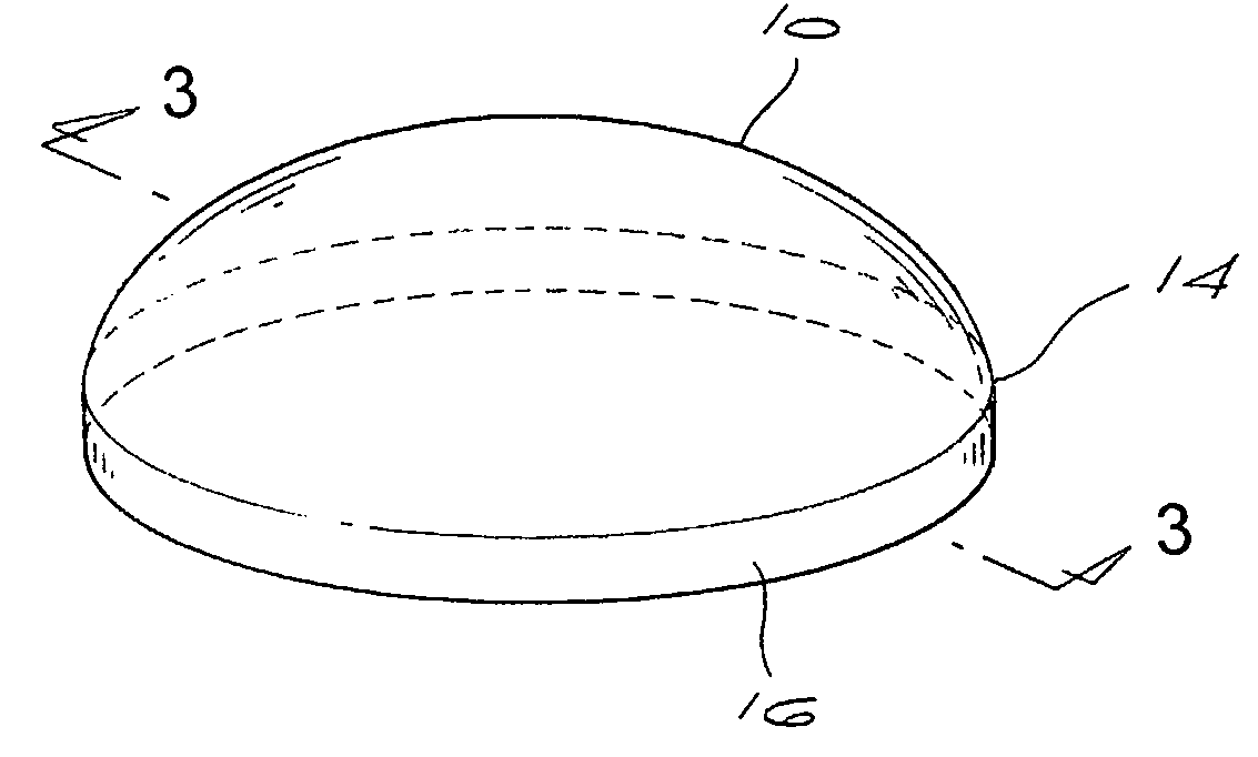
[0019]The invention extends further to a method of manufacturing a three-dimensional structure having relatively high rigidity and low mass comprising providing a source of ultra-hard abrasive particles or grit and a metal matrix material, compacting the ultra-hard abrasive particles or grit and the metal matrix material together to form a composite strip or foil, and shaping the composite strip or foil into the three-dimensional structure.

Problems solved by technology

However, larger drive units cannot easily be used to produce high frequency sounds due to the problems of unwanted oscillations or break-up that can occur.
Recently it has been demonstrated that the presence of break-up modes at frequencies that lie outside the accepted range of human hearing can cause audible degradation of the source.
Prior art records a variety of configurations of speaker dome, fabricated by a range of means, but the performance advantage reported is generally poor and such speaker domes are not in widespread use.

Method used


Image

  • Composite Material Comprising Ultra-Hard Particles Embedded in a Metal or Metal Alloy Matrix and Diaphragm Made Thereof
  • Composite Material Comprising Ultra-Hard Particles Embedded in a Metal or Metal Alloy Matrix and Diaphragm Made Thereof
  • Composite Material Comprising Ultra-Hard Particles Embedded in a Metal or Metal Alloy Matrix and Diaphragm Made Thereof

Examples


example 1

[0094]6 μm diamond grit in the as-crushed state was selected as the filler phase and cleaned chemically. The metal matrix was selected to be Al and this was prepared as 99.5% pure Al particles with an average particle size of 7-15 μm and a limit on the largest particles of <53 μm. The two components of the metal matrix material were then mixed in a mixing drum with the diamond forming 25% by volume, and then turned into a slurry by the addition of methyl cellulose in water. This was then cast onto a stainless steel support strip, dried and separated from the support strip to form a self-supporting film about typically 1.2 mm thick and 35-40% dense. This was reduced by the first rolling stage and annealing cycle to a layer about 0.45 mm thick and about 80% dense, after a second rolling and annealing cycle to 0.4 mm thick and about 99% dense, and a third rolling and annealing cycle to a fully dense layer about 0.35 mm thick. These annealing stages were typically at about 650° C. in ni...

example 2

[0095]The method of example 1 was followed except that the diamond grit was pre-coated with Ti to form a layer 20-30 nm thick by methods known in the art prior to mixing and compacting.

example 3

[0096]The method of example 1 was followed except that the filler comprised 6 μm diamond grit pre-coated with Ti as in example 2, to a total % by volume of 20%, and 0.6 μm cBN grit which was not coated, to a total of 15% by volume.


PUM

PropertyMeasurementUnit
thicknessaaaaaaaaaa
thicknessaaaaaaaaaa
thicknessaaaaaaaaaa

Abstract

A component that is rigid and three-dimensional and has a relatively low mass. The component has a foil body formed of a metal or metal alloy matrix that is embedded with ultra-hard particles or grit, such as diamond and / or cBN. It can be used in applications where a combination of high rigidity and low mass is required, such as in audio applications, for example.

Description

BACKGROUND OF THE INVENTION[0001]THIS invention relates to components, in particular audio components, which have high rigidity and low mass, and to composite materials used in their manufacture, and methods of manufacturing such composite materials and components.[0002]There are many applications requiring structures of high rigidity and low mass. Typical applications are in the aerospace industry where virtually all mechanical components must have a high rigidity to mass ratio.[0003]However, there is a range of other applications for light but rigid bodies. A particular application is the production of drive units for acoustic loudspeakers, and in particular high frequency tweeters for the accurate reproduction of high frequency sounds.[0004]Human hearing is commonly accepted to cover the range 20 Hz-20 kHz. Therefore a high quality loudspeaker system needs to accurately reproduce frequencies at least over this frequency range. Typical high performance loudspeakers employ two or m...

Claims


Application Information

Patent Timeline
Patent Type & Authority Applications(United States)
IPC IPC(8): H04R7/02C22C26/00
CPCC22C26/00H04R31/003Y10T428/12431H04R2307/027Y10T428/12H04R2307/023
Inventor SMALLMAN, CLINT GUYSCARSBROOK, GEOFFREY ALANDAVIES, GEOFFREY JOHNBRANDON, JOHN ROBERT
Owner SMALLMAN CLINT GUY
Learn More