Hub for a horizontal axis wind turbine

a technology of horizontal axis wind turbine and hub, which is applied in the direction of rotors, vessel construction, marine propulsion, etc., can solve the problems of insufficient cancellation of imbalance in strength in the reinforcement plate in patent reference 1, and the coupling of the reinforcement plate to the main shaft connection side of the hub is a drawback from the viewpoint of lighter weight, so as to achieve well-balanced strength and strengthen the hub tip. , the effect of balanced strength

Active Publication Date: 2008-05-22
HITACHI LTD
View PDF3 Cites 8 Cited by
  • Summary
  • Abstract
  • Description
  • Claims
  • Application Information

AI Technical Summary

Benefits of technology

[0030]According to the present invention, because of the off-center reinforcement and opening on the inside of the flange, relatively speaking, reinforcement of the tip of the hub becomes obvious with respect to the main shaft connecting side of the hub. Therefore, severe imbalances between the main shaft connecting side of the hub and the tip due to the casting mold of the hub are cancelled thereby making it possible to obtain a hub of a horizontal axis wind turbine with a well-balanced strength.
[0031]Because a balanced strength is obtained, there is no need to thicken the casing to strongly match the weak areas making it possible to pursue even thinner casing overall which in turn makes it easier to reduce the weight due to thinner casing.
[0032]Even further, by means of providing an opening at the area formed where the casing of the main shaft connection side of the hub is thick, that material will be omitted and thus, the weight can also be effectively reduced.

Problems solved by technology

The following problems exist for the conventional technology described above.
Nevertheless, compared to the lower area on the inlet side, the upper area of the exhaust side has a disadvantage in terms of strength.
If however, the main shaft connection side of the hub is established on the lower area of the casting mold, the main shaft connection side of the hub will have a relatively high strength and the tip of the hub will have a low strength resulting in an imbalance.
Because of this, there is a chance that the imbalance in strength in the reinforcement plate in Patent Reference 1 may not be sufficiently cancelled.
In addition, since the main shaft connection side of the hub is formed with a casing thickness of greater thickness, the coupling of the reinforcement plate to the main shaft connection side of the hub is a drawback from the viewpoint of lighter weight.
Therefore, the reinforcement plate in Patent Reference 2 cannot sufficiently cancel the imbalance in strength mentioned above.
Even further, since the casing thickness of the main shaft connection side of the hub is formed with a heavy thickness, the coupling of the reinforcement plate to the main shaft connection side of the hub is a drawback from the viewpoint of lighter weight.

Method used


Image

  • Hub for a horizontal axis wind turbine
  • Hub for a horizontal axis wind turbine
  • Hub for a horizontal axis wind turbine

Examples


first embodiment

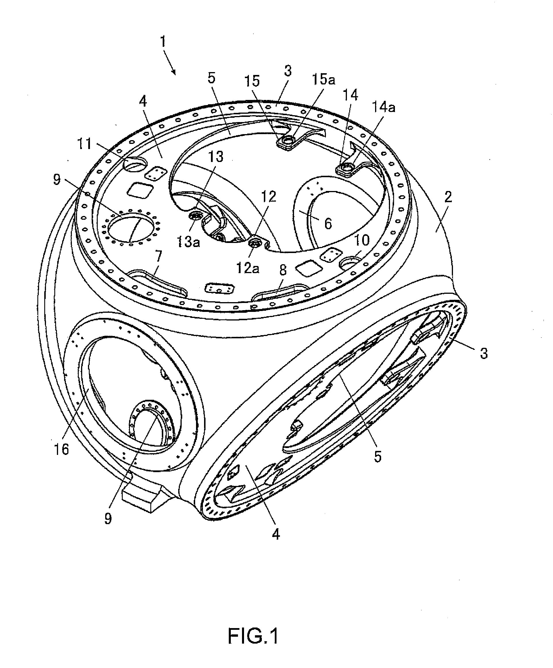
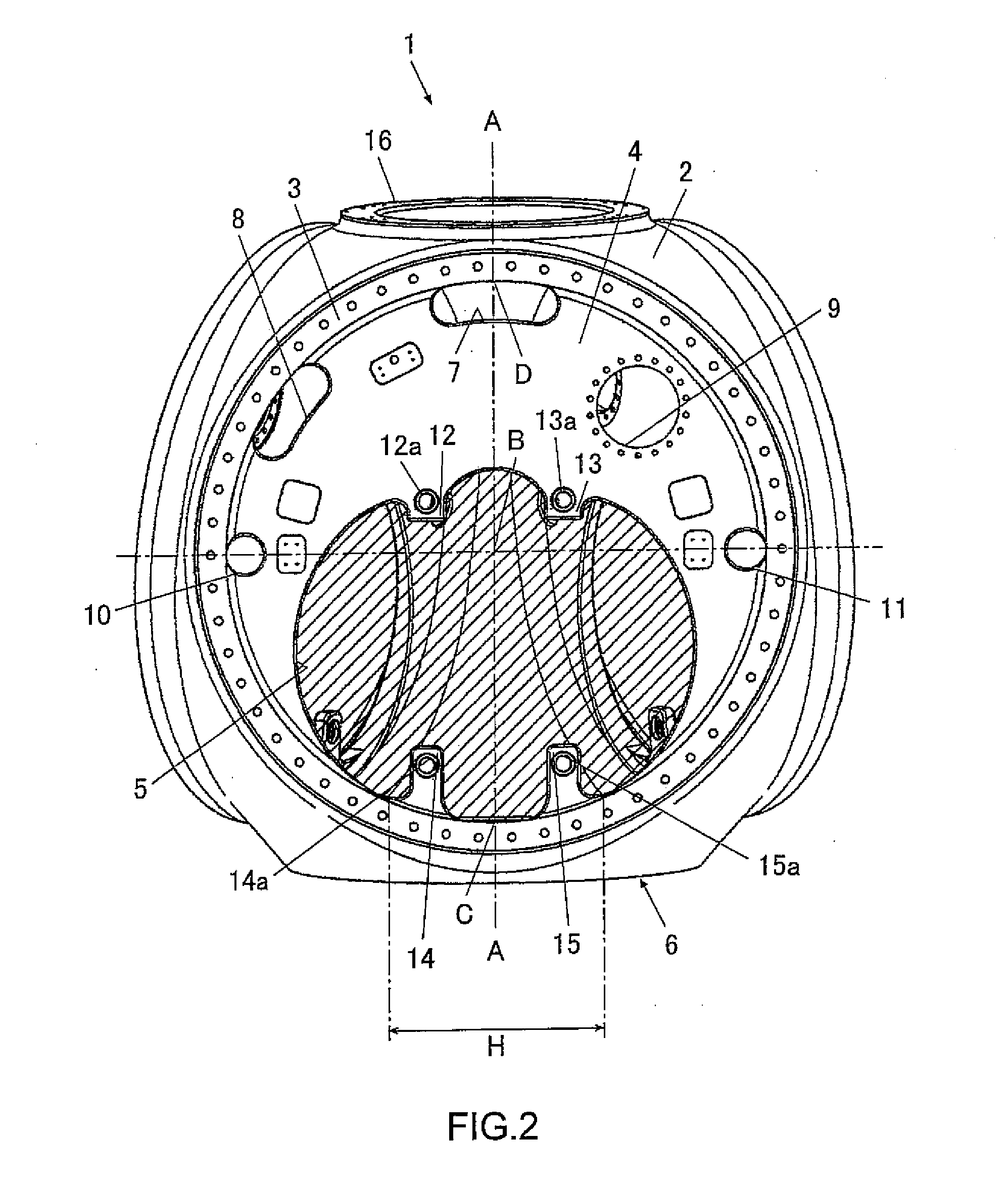
[0043]At first, a first embodiment of the present invention will be described referring to FIG. 1 to FIG. 4.

[0044]As shown in FIG. 1 to FIG. 3, the hub 1 of a horizontal axis wind turbine of this embodiment is comprised by the spherical shell 2, the circular flange 3, the reinforcement plate 4, the off-center opening 5, and the main shaft connecting part 6.

[0045]The spherical shell 2 is cut-out at the round region G inside the circular flange 3. In addition, the spherical shell 2 is also cut out at hole 6b of the main shaft connecting part 6 and tip hole 16.

[0046]The main shaft connecting part 6 has the stepped hole 6b at the center where the main shaft is fit in. A plurality of female threads 6a, 6a, . . . are provided at suitable locations on the peripheral edge. These female screws thread into bolts which secure the outer peripheral flange of the main shaft. Axis E-E is a center axis of the main shaft connected to the main shaft connecting part 6. The hole 6b of the main shaft co...

second embodiment

[0066]Next, a second embodiment of the present invention will be described referring to FIG. 5 to FIG. 6.

[0067]As shown in FIG. 5 and FIG. 6, the hub 51 of the horizontal axis wind turbine of this embodiment is comprised by the spherical shell 52, the circular flange 53, the reinforcement plate 54, the off-center opening 55, and the main shaft connecting part 56. Although the hub 51 of the horizontal axis wind turbine of this embodiment is almost the same as the first embodiment, the composition of the reinforcement plate and the holes inside the circular flange 53 is different as described below.

[0068]Similarly to the first embodiment, the center B of the circular flange 53 and the two intersection points C and D of the reference plane F and the peripheral edge of the round region G in this embodiment are shown in FIG. 6.

[0069]Although the off-center opening 55 is off center on the point C side as shown in FIG. 6, the off-center opening 55 is separated from the point C. In addition...


PUM


Abstract

To provide a lightweight hub of a horizontal axis wind turbine with a balanced strength, the hub 1 related to the present invention comprises a reinforcement plate 4 coupled to the spherical shell 2 on the peripheral edge in the round region G inside the circular flange 3 used to secure a blade. In addition to being off-center at the point C side, an off-center opening 5, that contains the center B of the region G, is formed in the region G. The reinforcement plate 4 is formed at the remainder portion of the region G after removing the off-center opening 5. By means of an unequal arrangement of the reinforcement plate 4 and the opening 5 on the inside of the circular flange 3, severe imbalances due to the casting of the hub 1 are cancelled and a balanced strength is obtained, making it also easier to reduce the weight.

Description

CROSS REFERENCE TO RELATED APPLICATIONS[0001]This application claims priority under 35 U.S.C. 119 based upon Japanese Patent Application Serial No. 2006-315629, filed on Nov. 22, 2006. The entire disclosure of the foresaid application is incorporated herein by reference.FIELD OF THE INVENTION[0002]The present invention relates to a hub of a horizontal axis wind turbine.BACKGROUND OF THE INVENTION[0003]At present, wind energy power conversion systems which utilize horizontal axis wind turbines with an objective of obtaining stable electrical power from natural wind have been proposed and put into practical use. As shown in FIG. 7 and FIG. 8, these horizontal axis wind turbines are comprised of a rotor that has a hub 21 and a blade 22, a nacelle 24 that axially supports the rotor through a main shaft 23 that extends in the approximate horizontal direction connected to the hub 21, and a tower installed in an approximate vertical direction along with supporting the nacelle 24. In additi...

Claims


Application Information

Patent Timeline
Patent Type & Authority Applications(United States)
IPC IPC(8): F03B3/14
CPCF03D1/001F03D1/0658F03D11/04F03D1/0691Y02E10/721Y02E10/728F05B2240/90F03D13/10F03D13/20Y02E10/72
Inventor KITA, MASAKAZUTOBINAGA, IKUOTOMIZAWA, ATSUKI
Owner HITACHI LTD
Why Eureka
Try Eureka