
On-Time Control For Constant Current Mode In A Flyback Power Supply

a constant current mode and power supply technology, applied in the field of power supply, can solve the problems of linear output voltage drop, cost to this solution, and reducing the overall system efficiency, and achieve the effect of convenient operation

Active Publication Date: 2008-05-15
DIALOG SEMICONDUCTOR INC
View PDF4 Cites 104 Cited by
  • Summary
  • Abstract
  • Description
  • Claims
  • Application Information

AI Technical Summary

Benefits of technology

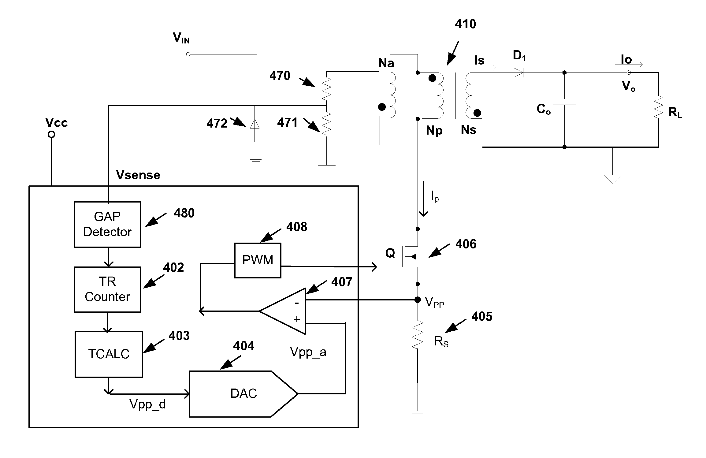
[0023]The present invention is a primary side sensing power control system and method for constant current control. Conventional systems use of the relationship between the square of the input line voltage, and the output voltage to determine the on-time and off-time for current regulation. The present invention utilizes a relationship that involves the measured reset-time from the previous cycle to determine the primary side peak current and off-time for the next cycle. This control mechanism does not need the knowledge of input voltage or magnetizing inductance. Therefore, it removes the sensitivities of input voltage and magnetizing inductance to the output current limit. Furthermore, it uses a time measurement instead of a voltage measurement for the current calculation which in many cases is easier to perform.

Problems solved by technology

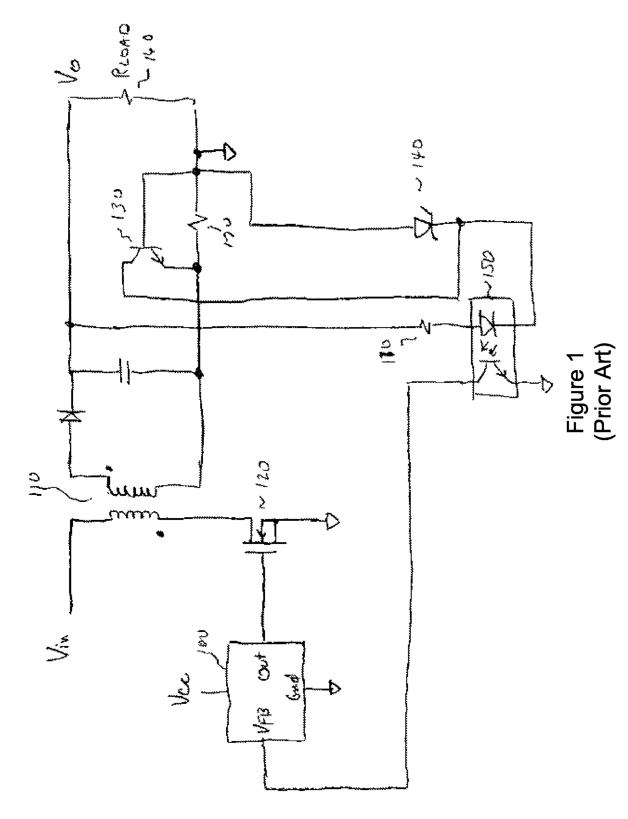
There are at least two significant drawbacks in cost to this solution.
The second drawback is the wasted power dissipated by the sense resistor, which reduces the overall system efficiency.
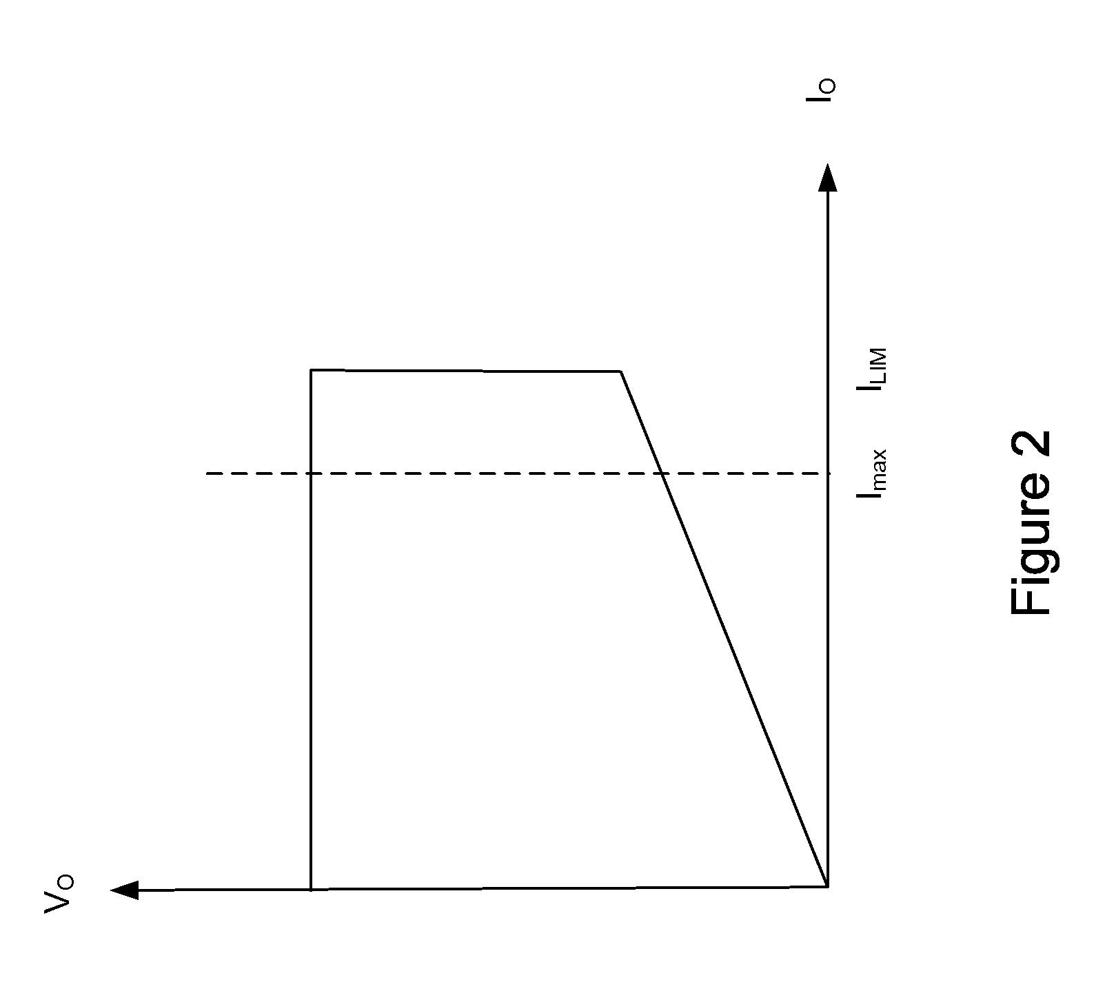
So the power requested by the increased output current is reduced which results in having the output voltage drop linearly.
Therefore, the system achieves a substantially constant output current limit with varying output voltage.
The multiplication of the VIN signal by itself is yet another complexity to the implementation.

Method used


Image

  • On-Time Control For Constant Current Mode In A Flyback Power Supply
  • On-Time Control For Constant Current Mode In A Flyback Power Supply
  • On-Time Control For Constant Current Mode In A Flyback Power Supply

Examples


Embodiment Construction

[0031]A preferred embodiment of the present invention is now described with reference to the figures where like reference numbers indicate identical or functionally similar elements. Also in the figures, the left most digit of each reference number corresponds to the figure in which the reference number is first used.

[0032]Reference in the specification to “one embodiment” or to “an embodiment” means that a particular feature, structure, or characteristic described in connection with the embodiments is included in at least one embodiment of the invention. The appearances of the phrase “in one embodiment” in various places in the specification are not necessarily all referring to the same embodiment.

[0033]Some portions of the detailed description that follows are presented in terms of algorithms and symbolic representations of operations on data bits within a computer memory and / or within a logic element. These algorithmic descriptions and representations are the means used by those ...


PUM


Abstract

A primary side sensing power control system and method for constant current control that utilizes a relationship that involves the measured reset-time from the previous cycle to determine the primary side peak current and off-time for the next cycle. This control mechanism does not need the knowledge of input voltage or magnetizing inductance. Therefore, it removes the sensitivities of input voltage and magnetizing inductance to the output current limit. Furthermore, it uses a time measurement instead of a voltage measurement for the current calculation which in many cases is easier to perform.

Description

RELATED APPLICATIONS[0001]This application is a continuation in part of U.S. application Ser. No. 11 / 558,326 filed on Nov. 9, 2006 which is incorporated by reference herein in its entirety.FIELD OF THE INVENTION[0002]The present invention is related to a power supply and more particularly to pulse width modulation (PWM) and pulse frequency modulation (PFM) controllers for limiting current with primary-side sensing and feedback.BACKGROUND OF THE INVENTION[0003]Pulse width modulation (PWM) is a conventional technology used for controlling power converters to achieve output power, voltage, and current regulation. Conventional flyback power converters include a power stage for delivering electrical power from a power source to a load, a switch in the power stage that electrically couples or decouples the load to the power source, and a switch controller coupled to the switch for controlling the on-time and off time for the switch. The on-time (TON) and off-time (TOFF) for the switch can...

Claims


Application Information

Patent Timeline
IPC IPC(8): H02M3/335
CPCH02M2001/0006H02M3/33515H02M1/0006
Inventor YAN, LIANGZHENG, JUNJIEKESTERSON, JOHNWANG, XIAOYANBUI, HIEN
Owner DIALOG SEMICONDUCTOR INC
Learn More