
Advanced Digital Receiver

a digital receiver and advanced technology, applied in the field of digital communication techniques, can solve problems such as improper reception, corrupted sent messages, and uncertainty as to the content of original messages

Active Publication Date: 2008-05-08
ENTROPIC COMM INC
View PDF59 Cites 37 Cited by
  • Summary
  • Abstract
  • Description
  • Claims
  • Application Information

AI Technical Summary

Problems solved by technology

Channel noise often interferes with the transmission and degrades the transmitted message and leads to some uncertainty as to the content of the original message at the receiver.
Those conditions that interfere with proper reception include additive white Gaussian noise (AWGN) and coherent noise, frequency dependent channel distortion, time dependent channel distortion, and fading multipath.
Because of these effects, there is some probability that the sent message is corrupted when it reaches the receiver.
This requires the receiver design to overcome the problems associated with system synchronization, as related to symbol-timing and carrier recovery, under non-ideal transmission channel conditions.
The propagation delay in the transmitted signal also results in a carrier phase offset.
Any phase-locking mechanism has some finite delay in practice so that the mechanism attempts to predict the incoming phase and then measures the accuracy of that prediction in the form of a new phase error.
The more quickly the phase-lock mechanism tracks deviations in phase, the more susceptible the mechanism is to random noise and other imperfections.
As previously described, the PLL subsystem is insufficient to recover the symbol rate.
Improper symbol-timing recovery is one source of intersymbol interference (ISI) and significantly degrades the performance of the receiver.
Excessive delay degrades the overall performance of the receiver or, in the worst-case, causes the phase-locked loop to become unstable.
There are numerous sources of channel distortion and interference that may result in poor receiver performance, as measured by either bit error rate (BER) or overall data transfer rates of a receiver design.
Fading is due to the propagation delay associated with each propagation path resulting in constructive and destructive interference at the receiver.
Fast fading is very difficult to compensate effectively.
As a consequence, the baseband pulse shape is distorted and intersymbol interference results.
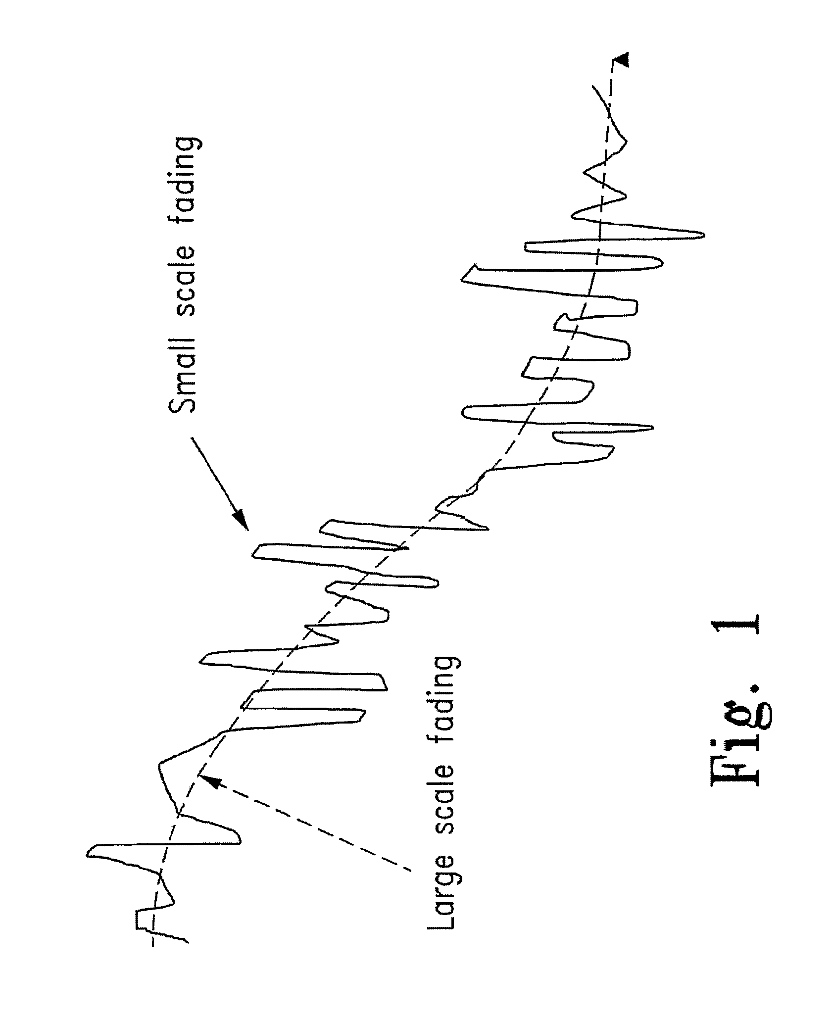
Large motions of the receiver, such as occur in mobile applications, cause large-scale fading, whereas small-scale fading is due to motion of the receiver.
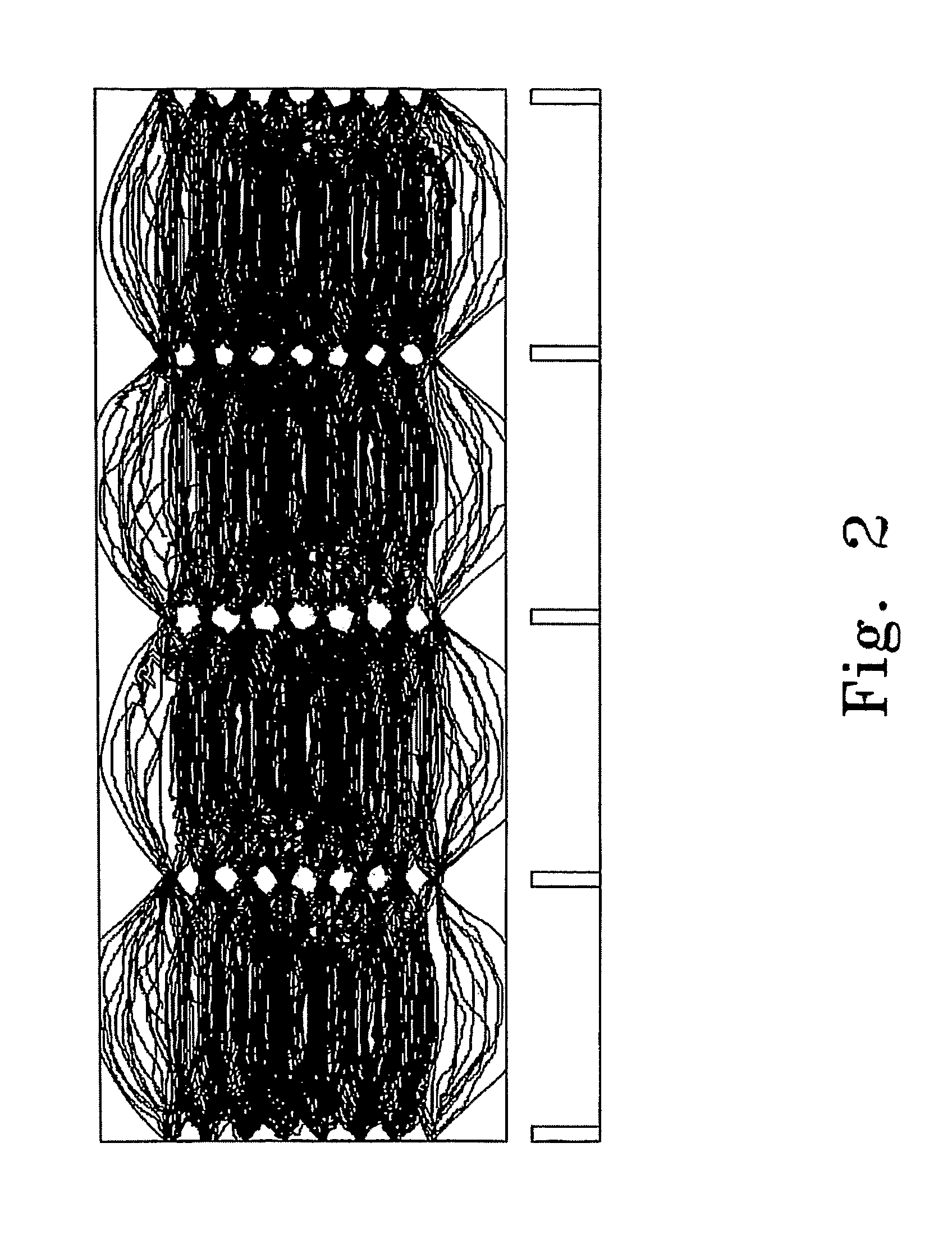
If the 8-VSB signal is corrupted during transmission, these “eyes” will close up and disappear, as the RF signal will no longer possess the correct amplitude at the right instant.
Obtaining an ideal channel estimate, however, is problematic when presented with particularly odious channel characteristics.
Despite the numerous techniques available in the present state of the art, receivers exhibit significant performance degradation in the presence of strong multipath environments.
This has a distinct disadvantage in a changing multipath fading environment.
Also, the receiver can lose lock as the strength of the primary multipath signal fades or a new stronger signal appears.
Changing multipath conditions thus often necessitate a receiver to reacquire carrier lock, resulting in a possibly noticeable disruption in information flow to a user at the receiver.

Method used


Image

  • Advanced Digital Receiver
  • Advanced Digital Receiver
  • Advanced Digital Receiver

Examples


Embodiment Construction

[0091]For the purposes of promoting an understanding of the principles of the invention, reference will now be made to the embodiments illustrated in the drawings and specific language will be used to describe the same. It will nevertheless be understood that no limitation of the scope of the invention is thereby intended. Any alterations to and further modification of the described embodiments, and any further applications of the principles of the invention as described herein are contemplated as would normally occur to one skilled in the art to which the invention relates.

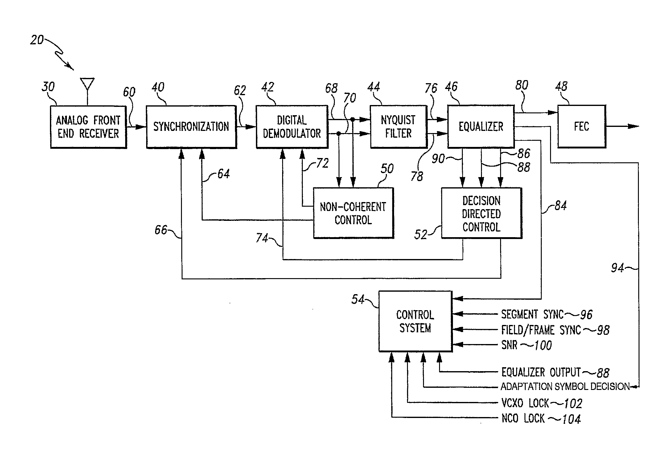
[0092]One aspect of the present system illustrated in FIG. 3 is a digital receiver system with significantly improved stability and performance when receiving modulated signals in severe multipath environments. The techniques, devices, and systems embodied in this new digital receiver may be adapted to various modulation formats, including, but not limited to, QAM, offset-QAM and VSB. Illustratively, one non-limi...


PUM


Abstract

A digital receiver for processing a signal received from a channel includes a digital demodulator and an equalizer coupled to the digital demodulator. The equalizer includes a feedforward filter and a decision feedback equalizer (DFE), wherein the feedforward filter includes a plurality of feedforward filter taps. Coefficients are associated with the plurality of feedforward filter taps and the values of all of the coefficients associated with the plurality of feedforward filter taps are dynamically determined.

Description

CROSS REFERENCE TO RELATED APPLICATIONS[0001]This application claims the benefit of U.S. Provisional Application No. 60 / 561,085, filed Apr. 9, 2004, and entitled “Advanced Digital Receiver” and further claims the benefit of U.S. Provisional Application No. 60 / 601,026, filed Aug. 12, 2004, and entitled “Advanced Digital Receiver.” The present application also incorporates by reference U.S. application Ser. No. 10 / 408,053, filed Apr. 4, 2003, and entitled “Carrier Recovery for DTV Receivers,” U.S. application Ser. No. 09 / 875,720, filed Jun. 6, 2001, and entitled “Adaptive Equalizer Having a Variable Step Size Influenced by Output from a Trellis Decoder,” (now U.S. Pat. No. 6,829,297), U.S. application Ser. No. 10 / 407,634, filed Apr. 4, 2003, and entitled “System and Method for Symbol Clock Recovery,” U.S. application Ser. No. 09 / 884,256, filed Jun. 19, 2001, and entitled “Combined Trellis Decoder and Decision Feedback Equalizer,” and U.S. application Ser. No. 10 / 407,610, filed Apr. 4,...

Claims


Application Information

Patent Timeline
IPC IPC(8): H04L27/01
CPCH04L1/006H04L7/0062H04L25/03057H04L25/0212H04L7/042
Inventor XIA, JINGSONGCHEN, SHIDONGCITTA, RICHARD W.KRISHNAMURTHY, GOPALANLOPRESTO, SCOTT M.WILLMING, DAVID A.YANG, XIAOJUNZHU, JILIAN
Owner ENTROPIC COMM INC
Learn More