
Objective lens optical system

Inactive Publication Date: 2008-05-08
HITACHT MAXELL LTD
View PDF0 Cites 3 Cited by
  • Summary
  • Abstract
  • Description
  • Claims
  • Application Information

AI Technical Summary

Benefits of technology

[0014] Thus, with the structure in which both the compatible techniques A and B are applied, it becomes possible to achieve compatibility in the case of the same wavelengths, and to improve the light use efficiency and reduce stray light in the compatibility in the case of different wavelengths, thereby providing an objective lens optical system of high performance.
[0044] According to the present invention, it is possible to improve the light use efficiency and reduce stray light of an objective lens optical system in which wavelengths of light beams to be focused on at least two or more optical recording medium are the same, wavelengths of light beams to be focused on at least two or more optical recording medium are different, and light beam is focused on at least three or more optical recording medium, and thereby providing the objective lens optical system of high performance.

Problems solved by technology

However, it is difficult to apply this compatible technique in the case of focusing light of the same wavelength on optical recording medium having different thicknesses.
Therefore, there are problems of increasing in the number of parts, and in the size and weight of the objective lens optical system.
However, since each area of the objective lens optical system for focusing light on each optical recording medium can focus the light only on respective optical recording medium, if focusing the light on three or more optical recording medium, problems such as a laser power increase due to lowering of the light use efficiency, and processing of stray light will occur.
However, since a diffractive structure is used for a compatible technique of this area, the light use efficiency is lowered because of the diffraction efficiency, which still results in the problem of a laser power increase due to lowering of the light use efficiency and processing of stray light.
As described above, in the case of applying such objective lens optical system to the conventional technique, there has been occurred the problem, such as a laser power increase due to lowering of the light use efficiency, and processing of stray light.

Method used


Image

  • Objective lens optical system
  • Objective lens optical system
  • Objective lens optical system

Examples


embodiment 1

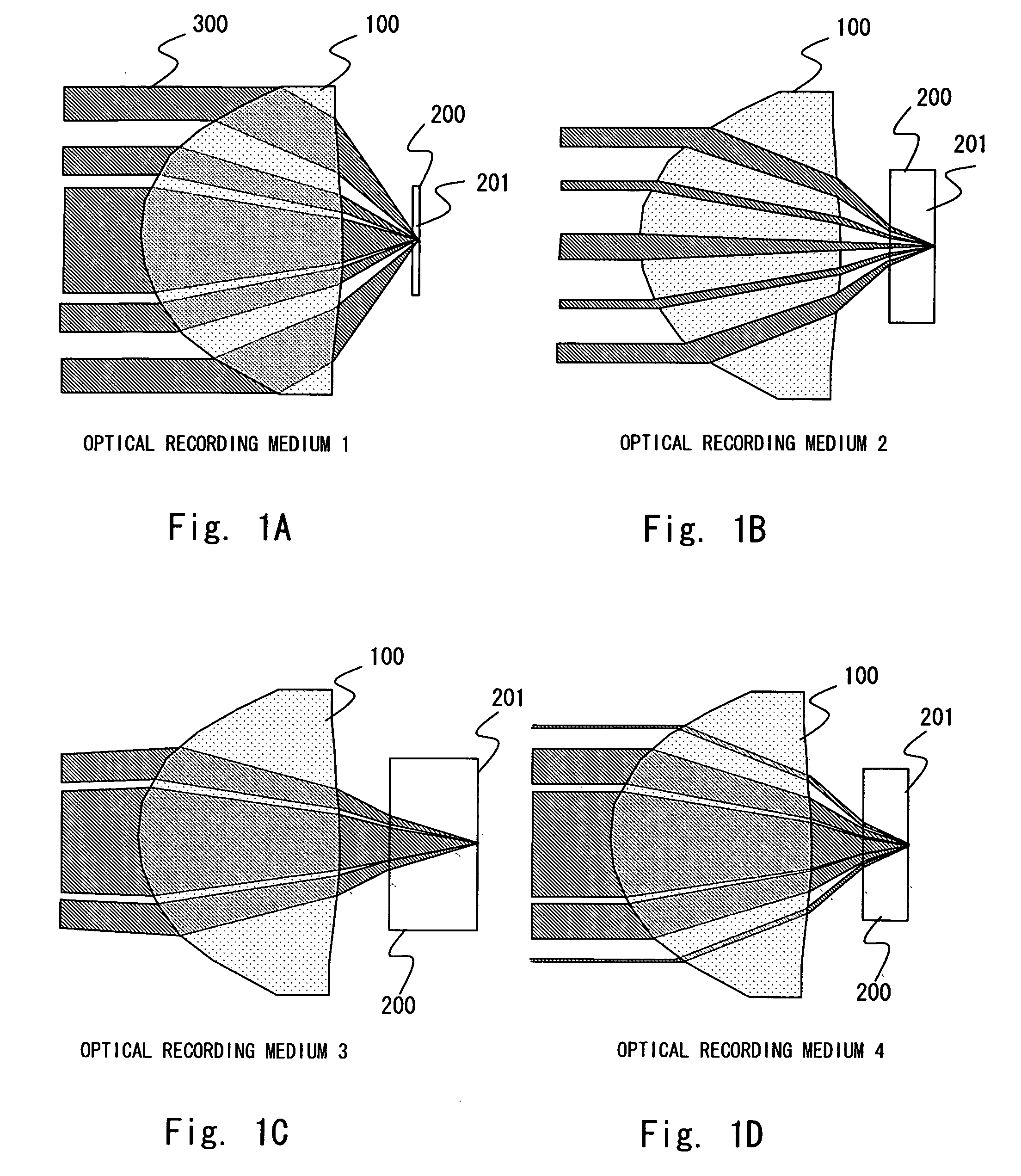
[0108] The objective lens optical system according to the present Embodiment 1 is composed of one lens. With respect to this objective lens, an effective aperture of an incident light beam into each of the optical recording medium and a refractive index of lens material used are shown in FIG. 12.

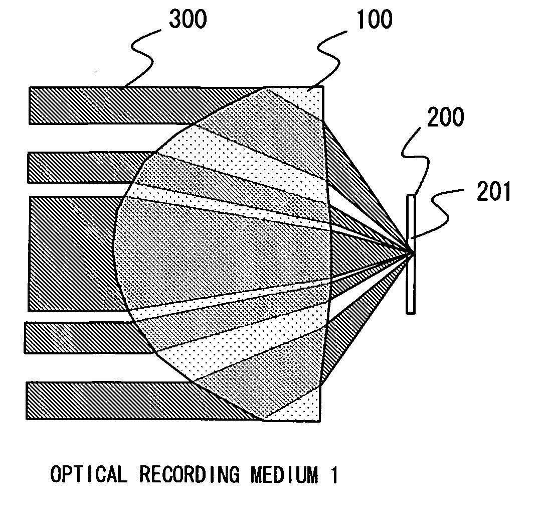
[0109]FIG. 13 shows areas of light height for focusing light on each of the optical recording medium. The number for each area will be hereinafter called a “medium area number.” For example, a medium area number 1 is an area specified by a light height of 0 to 0.232 mm, and a medium area number 2 is an area specified by a light height of 0.232 to 0.725 mm. The light height is a distance from an optical axis which is perpendicular to an optical axis on the iris surface.

[0110] According to Embodiment 1, as shown in FIG. 13, focusing light on each of the optical recording medium shown in FIG. 13 can be performed in the area specified by the medium area number. Concretely, the area specified b...

embodiment 2

[0124] The objective lens optical system according to the present Embodiment 2 has the same basic structure as that of Embodiment 1, in which light is focused on the four types of the optical recording medium shown in FIG. 11, and a lens material is used which has the effective apertures and the refractive indexes of an incident light beam to be input into each of the optical recording medium shown in FIG. 12. Hereafter, description is omitted for the same contents as those of Embodiment 1.

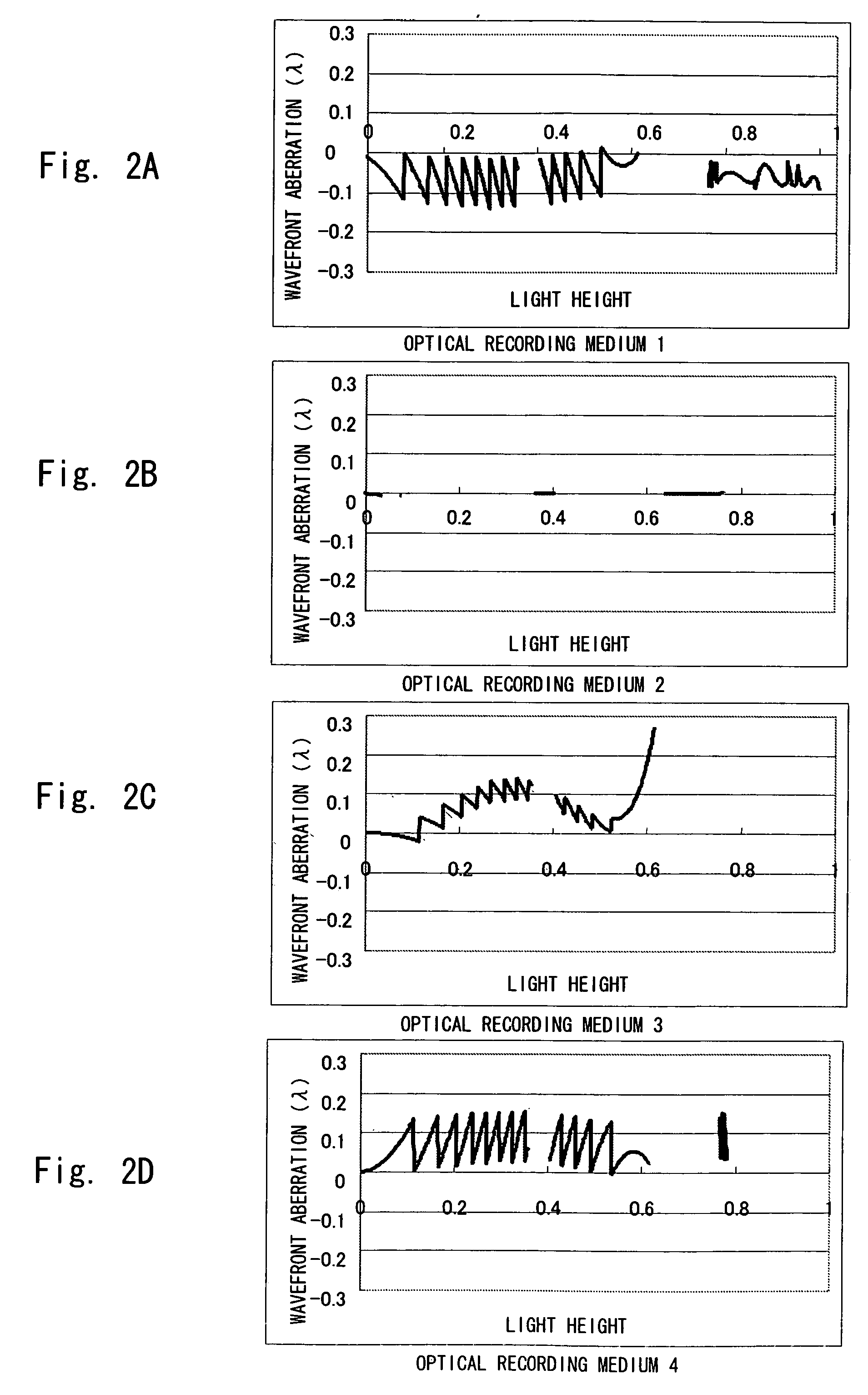
[0125]FIG. 18 shows areas of light height for focusing light on each of the optical recording medium in the objective lens optical system according to Embodiment 2. FIGS. 19 and 20 show lens data and surface shape data of the lens of the objective lens optical system according to Embodiment 2. FIG. 3 shows wavefront aberrations of the objective lens optical system according to Embodiment 2, and FIG. 22 shows an RMS wavefront aberration value concerning the objective lens optical system according ...

embodiment 3

[0129] According to Embodiment 3 described below, the objective lens optical system of the present Embodiment has the same basic structure as that of Embodiment 1, in which light is focused on the four types of the optical recording medium by using the objective lens optical system shown in FIGS. 23-27. FIG. 4 shows features of the objective lens optical system according to Embodiment 3, and FIG. 28 shows RMS wavefront aberration values. Hereafter, the description is omitted for the same contents as those of Embodiment 1.

[0130] In the objective lens optical system according to Embodiment 3, an optical path length difference between areas is arranged as follows: That is, with respect to the areas specified by the surface area numbers 2, 4, 6, 12, and 14, an optical path length difference is set to be approximately −0.06±0.06λ, that is −0.12λ2 to 0λ2 for the optical recording medium 2, and an optical path length difference is set to be approximately +0.06±0.06λ, that is 0λ4 to 0.12λ4...


PUM


Abstract

An objective lens optical system focuses a light beam with a wavelength λ1 on an information recording surface of a first optical recording medium including a transparent substrate with a thickness t1, a light beam with the wavelength λ1 on an information recording surface of a second optical recording medium including a transparent substrate with a thickness t2, and a light beam with a wavelength λ3 on an information recording surface of a third optical recording medium including a transparent substrate with a thickness t3, by using a refraction action. Sectioning the area of the objective lens optical system is applied to a compatible technique for the same wavelengths, and generating an aberration for canceling a chromatic aberration caused by a difference in wavelength λ of the light beam is applied to a compatible technique for different wavelengths.

Description

BACKGROUND OF THE INVENTION [0001] 1. Field of the Invention [0002] The present invention relates to an objective lens optical system or an optical pickup optical system capable of recording or reproducing data on / from a plurality of types of optical recording medium each having a different thickness. [0003] 2. Description of Related Art [0004] Conventionally, an objective lens optical system for focusing light on different optical recording medium has been developed. For example, there is disclosed a technique in Japanese Patent Application Laid-open No. 2001-195769 that focuses light on two different optical recording medium by utilizing a chromatic aberration caused by a wavelength difference and a wavefront aberration caused by thickness of a transparent substrate (hereinafter called a compatible technique). However, it is difficult to apply this compatible technique in the case of focusing light of the same wavelength on optical recording medium having different thicknesses. [0...

Claims


Application Information

Patent Timeline
IPC IPC(8): G11B7/135G11B7/125
CPCG02B3/02G11B7/1275G11B7/1367G11B2007/13722G11B7/13922G11B2007/0006G11B7/1374G02B13/00G02B13/18G02B3/00
Inventor KANAI, TOMONORIMARUYAMA, TAKESUKEWAKABAYASHI, KOICHIROMITSUI, YOSHIKAZUMIYAUCHI, MITSUHIROSUGI, YASUYUKI
Owner HITACHT MAXELL LTD
Learn More