Eureka AIR delivers breakthrough ideas for toughest innovation challenges, trusted by R&D personnel around the world.

Boat Lifting Apparatus and Method

Inactive Publication Date: 2008-05-08
SEALIFT INCORPORATED
View PDF51 Cites 14 Cited by
  • Summary
  • Abstract
  • Description
  • Claims
  • Application Information

AI Technical Summary

Benefits of technology

[0009] Embodiments of the present invention provide a practical, efficient, simple and easy to operate lifting apparatus and system for raising and lowering watercrafts such as jet skis, inflatables, rowboats, personal watercrafts, and the like, and other vessels from swim platforms on the back of larger pleasure crafts, docks, bulkheads, and the like.
[0010] Embodiments of the present invention may employ only a single actuator, which actuator may include a single fluid cylinder and single fluid operated piston. A cradle may include supports that avoid marring or damaging the underside of the watercrafts being raised and lowered.
[0012] The rotatable crank may include a rotatable crank shaft with a crank bracket fixably attached to the rotatable crank shaft, the one end of the fluid operated actuator pivotably attached to the crank bracket and the first end of the arm fixably attached to the rotatable crank shaft. The arm supporting the cradle may include a telescoping section that allows the arm to have a varying length.

Problems solved by technology

However, they are also well known to have limitations and problems that affect their applications.
However, the lines and pulleys and blocks and tackle required can easily become tangled, and difficult to operate.
Also, these old type devices generally require hand operated cranks that are not desirable nor efficient or practical for the person operating these lift devices.
Still furthermore, the fixed platforms and cradles used are also problematic since many include surfaces which may scratch, mar and damage the hulls and bottoms of the small type boats.
Many current type small craft boat lifts require complex and expensive arrangements of plural hydraulic type cylinders to raise and lower a platform or fixed cradle.
The fixed platforms and cradles used are also problematic since many include surfaces which may scratch, mar and damage the hulls and bottoms of the small type boats.

Method used


Image

  • Boat Lifting Apparatus and Method
  • Boat Lifting Apparatus and Method
  • Boat Lifting Apparatus and Method

Examples


Embodiment Construction

[0049] The present invention will now be described more fully hereinafter with reference to the accompanying drawings, in which preferred embodiments of the invention are shown. This invention may, however, be embodied in many different forms and should not be construed as limited to the embodiments set forth herein. Rather, these embodiments are provided so that this disclosure will be thorough and complete, and will fully convey the scope of the invention to those skilled in the art. Like numbers refer to like elements throughout, and prime notation is used to indicate similar elements in alternate embodiments.

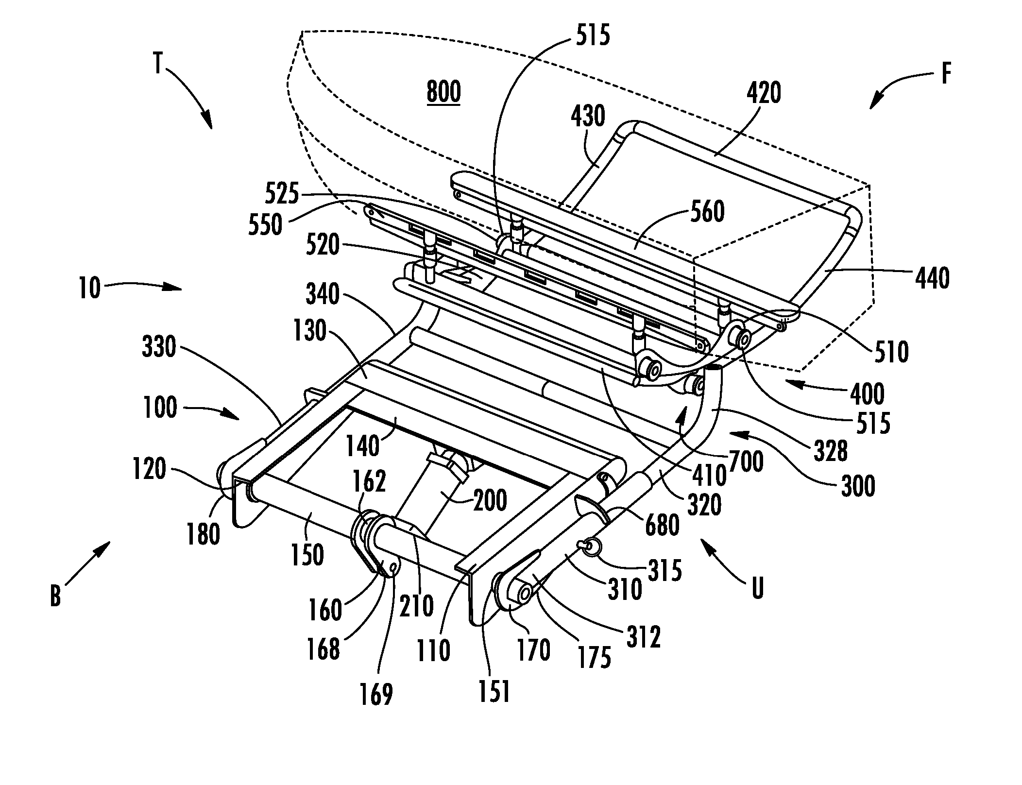
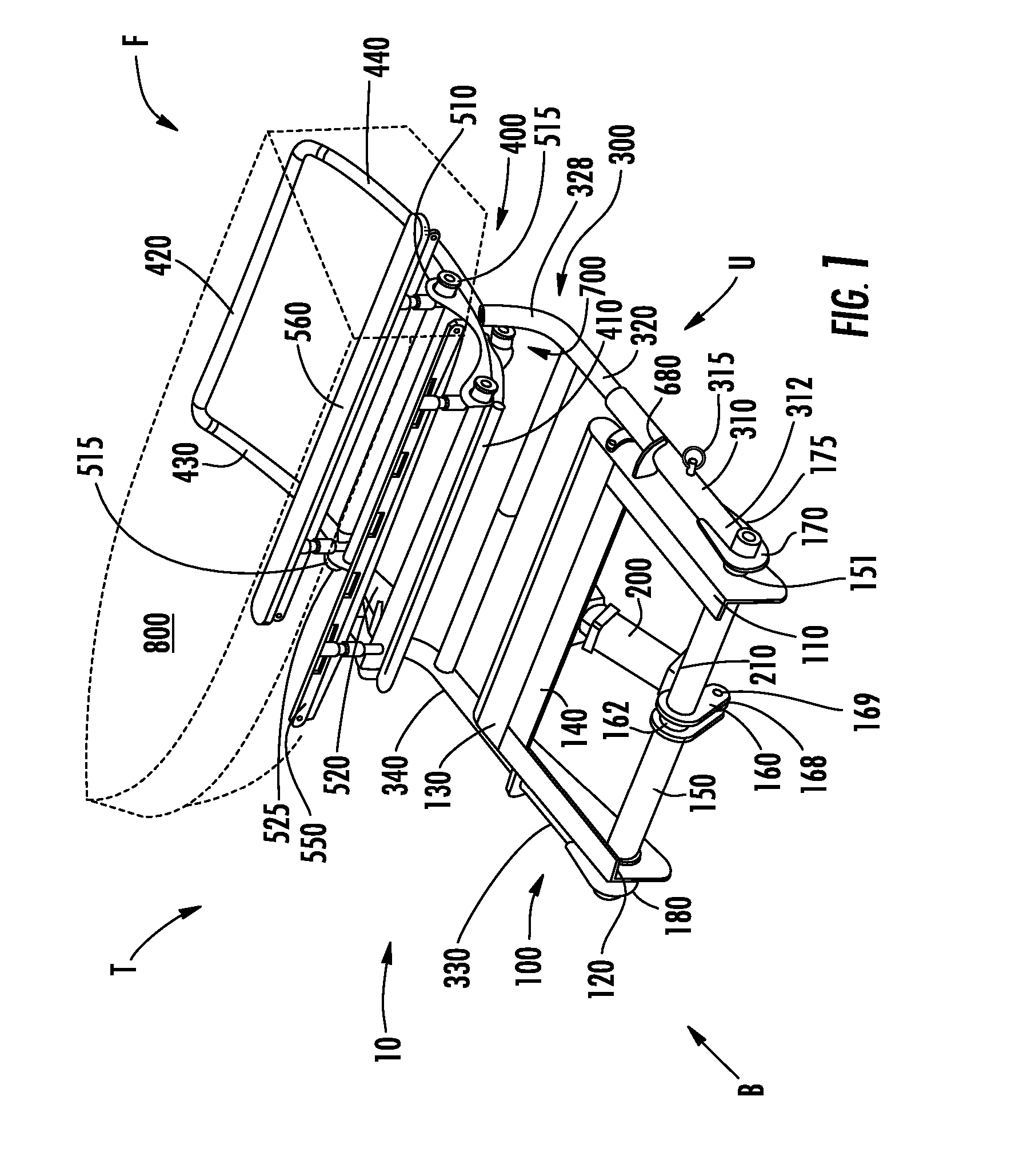
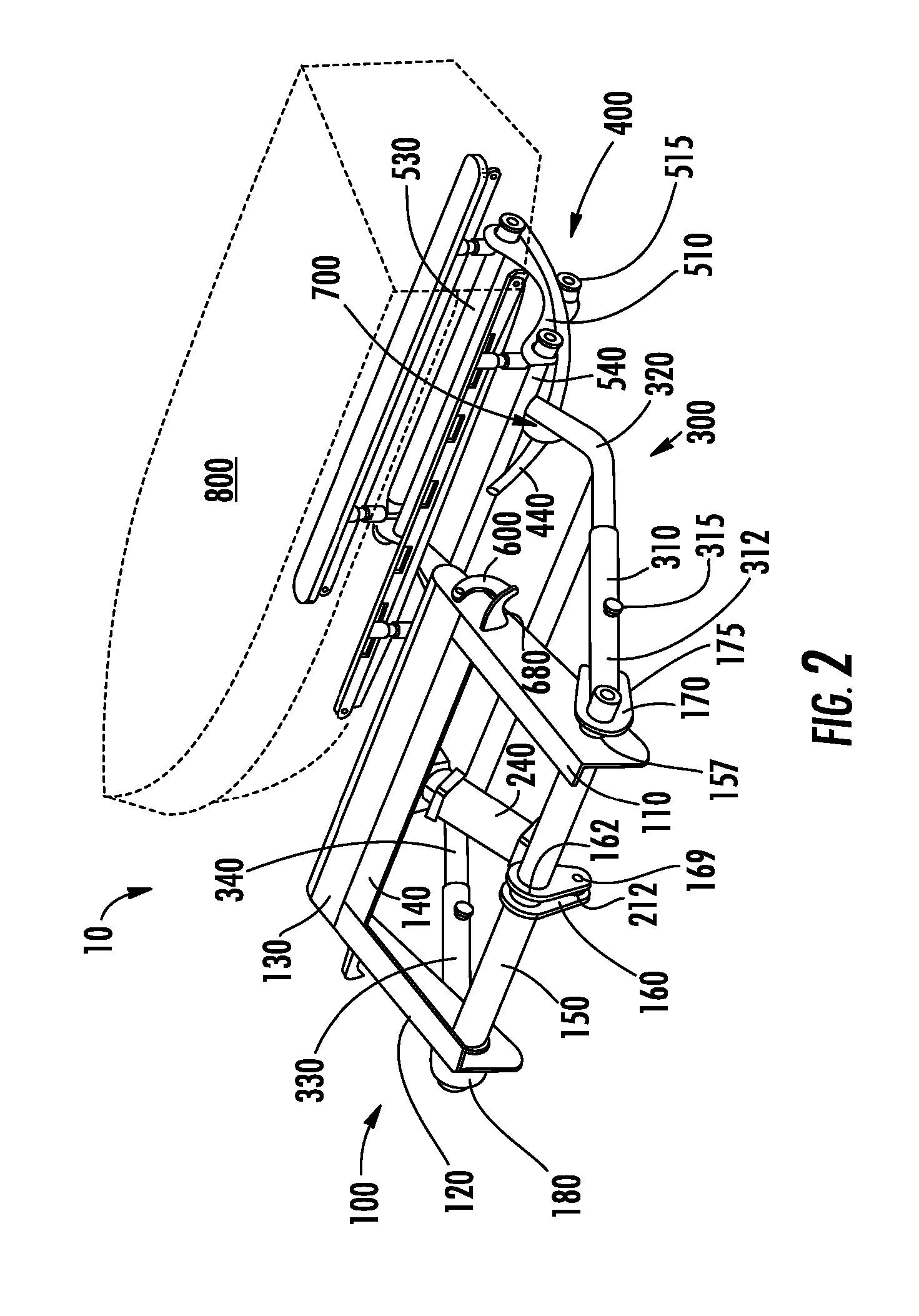
[0050] Referring initially to FIG. 1, a lifting apparatus 10 in keeping with the teachings of the present invention is herein described by way of example. FIG. 1 is a back perspective view of the lift 100 in an up position FIG. 2 is a back perspective view of the lift 100 of FIG. 1 in a down position. FIG. 3 is a side view of the lift 100 of the preceding figures in an up p...


PUM


Abstract

A lifting apparatus for raising and lowering a vessel such as personal watercraft, jet skis, inflatables may be mounted to a transom on boats, to bulkheads and to docks for raising and lowering vessels. A single actuator is used for raising and lowering a cradle that supports the vessel. An arm driven by the actuator is pivotally mounted to a mounting bracket and is extendable to different lengths. The cradle includes a self-leveling carriage that may use rollers to roll on a curved surface of the cradle allowing the supported watercraft to remain in a substantially level position thereon. An adjustable swivel mount is used to adjust the cradle to a desired horizontal orientation.

Description

CROSS-REFERENCE TO RELATED APPLICATIONS [0001] This application is a continuation-in-part application and claims the benefit of U.S. application Ser. No. 11 / 090,827 for “Hydraulic Transom Lift,” filed May 10, 2005 and issuing as U.S. Pat. No. 7,293,521, the disclosure of which is hereby incorporated by reference herein in its entirety, and commonly owned.FIELD OF THE INVENTION [0002] The present invention relates to watercrafts and in particular to devices, apparatus and systems for raising and lowering watercrafts such as jet skis, inflatables, rowboats, small personal watercrafts, and the like, as well as other types of vessels from swim platforms on the back of larger pleasure crafts, from docks, from bulkheads, and the like. BACKGROUND OF THE INVENTION [0003] Small craft lift devices for raising and lowering small craft type boats into and out of the water which can be mounted off larger boats are well known. However, they are also well known to have limitations and problems tha...

Claims


Application Information

Patent Timeline
IPC IPC(8): B63B35/40B66C13/00
CPCB63B23/32B63B27/16B63B27/36
Inventor JOHNS, CARL E. JR.JOHNS, STEPHEN G.
Owner SEALIFT INCORPORATED
Why Eureka
Eureka Blog
Learn More