Broadband antenna

a broadband antenna and antenna technology, applied in the field of broadband antennas, can solve the problems of inconvenient carrying or use of the unit, antennas are extended for a set length, time and work consumptive, etc., and achieve the effect of wide bandwidth

Inactive Publication Date: 2008-05-01
CHANT SINCERE
View PDF3 Cites 0 Cited by
  • Summary
  • Abstract
  • Description
  • Claims
  • Application Information

AI Technical Summary

Benefits of technology

[0007]The present invention provides a broadband antenna, it includes structurally a low-frequency antenna path, a high-frequency antenna path connected with the low-frequency antenna path, and a coaxial cable for feeding out a signal; the core line of the coaxial cable for signal transmission is connected with a signal feed-in point of the antenna, but a grounding line of the coaxial cable is not connected with the antenna to avoid making the coaxial cable a parasitic element of the antenna; the coaxial cable is arranged parallely to the low-frequency antenna path or the high-frequency antenna path, the grounding line of the coaxial cable is used to do perturbation against the transmission path of the antenna, thereby the antenna can get an effect of a broad bandwidth.

Problems solved by technology

Such a conventional coil antenna is stable and reliable in emitting and receiving signals, but it is time and work consumptive and cost higher in manufacturing; the largest problem of it is that the antenna is extended out for a set length.
Communication units used nowadays include mobile phones and notebooks, most of them are portable electronic products, if an antenna is extended out the surface of a unit, the unit will be inconvenient for carrying or using.
However, no matter which kind of microstrip circuit is used, such microstrip antennas used presently all have only narrower bandwidths and lower irradiation efficiencies, thus improvement is required.

Method used


Image

  • Broadband antenna
  • Broadband antenna
  • Broadband antenna

Examples


Embodiment Construction

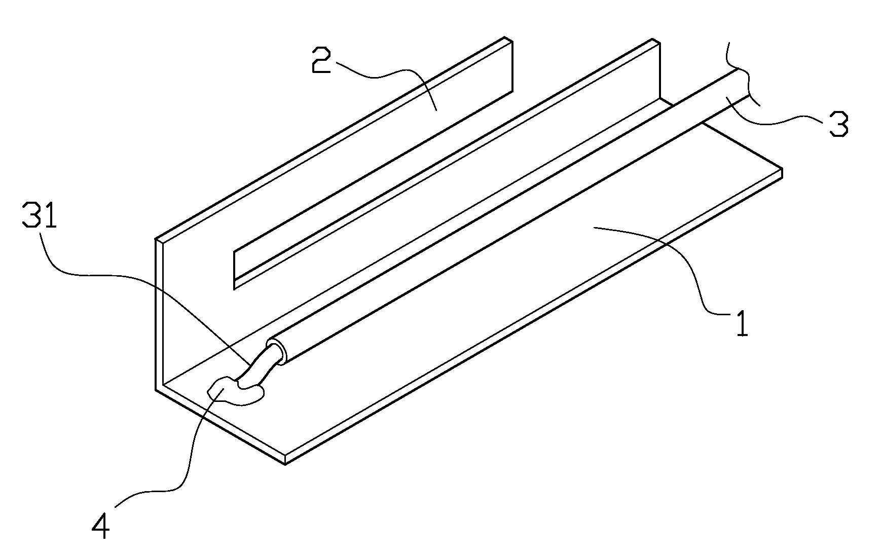
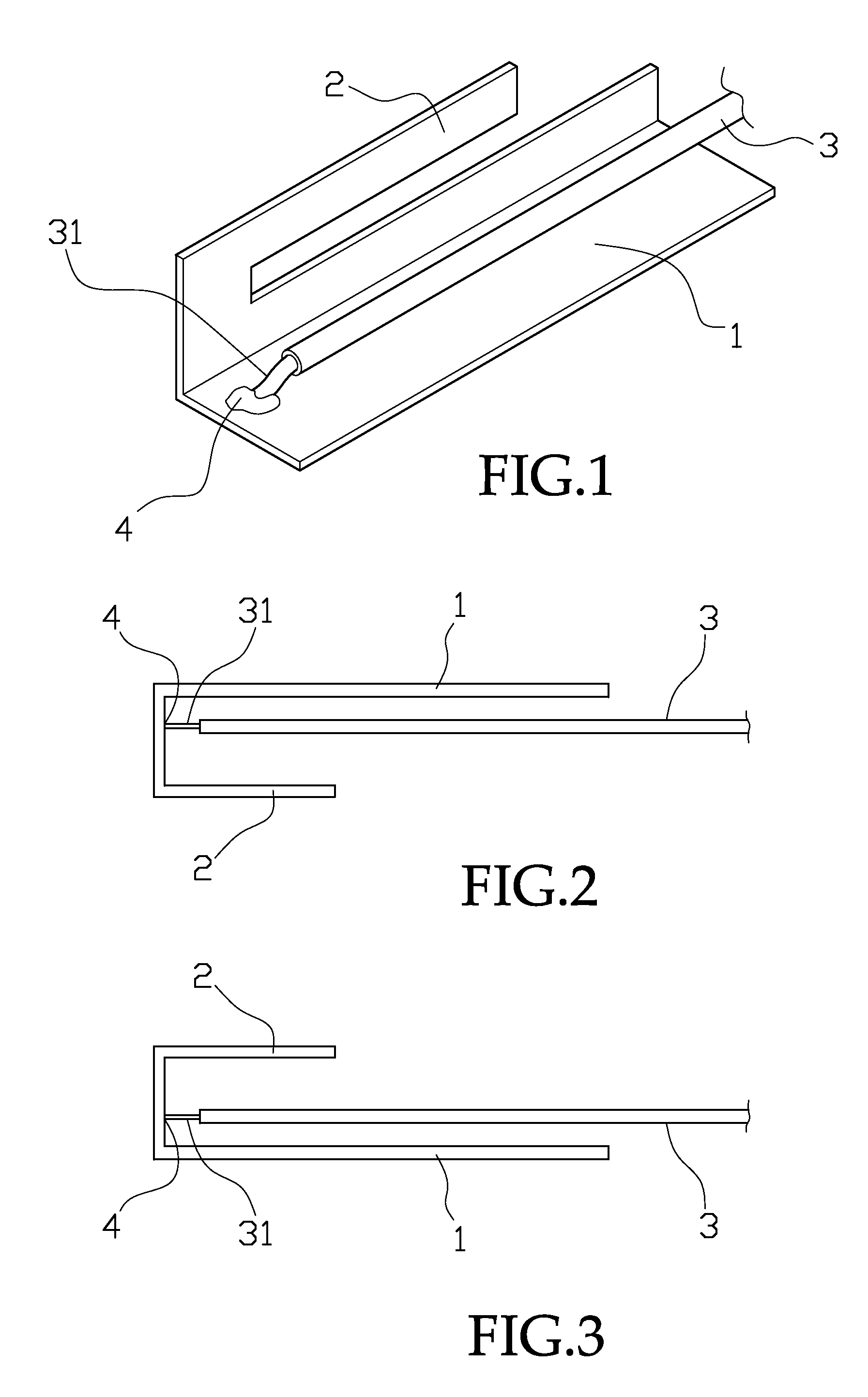
[0018]Referring to FIG. 1, a broadband antenna provided by the present invention includes structurally a low-frequency antenna path 1, a high-frequency antenna path 2 connected with the low-frequency antenna path 1, and a coaxial cable 3 of for feeding out a signal.

[0019]The range of frequency band used for the antenna is divided into a low-frequency band and a high-frequency band, then ¼ wave lengths (λ / 4) of the low- and the high-frequency bands are calculated to be the low-frequency antenna path 1 and the high-frequency antenna path 2.

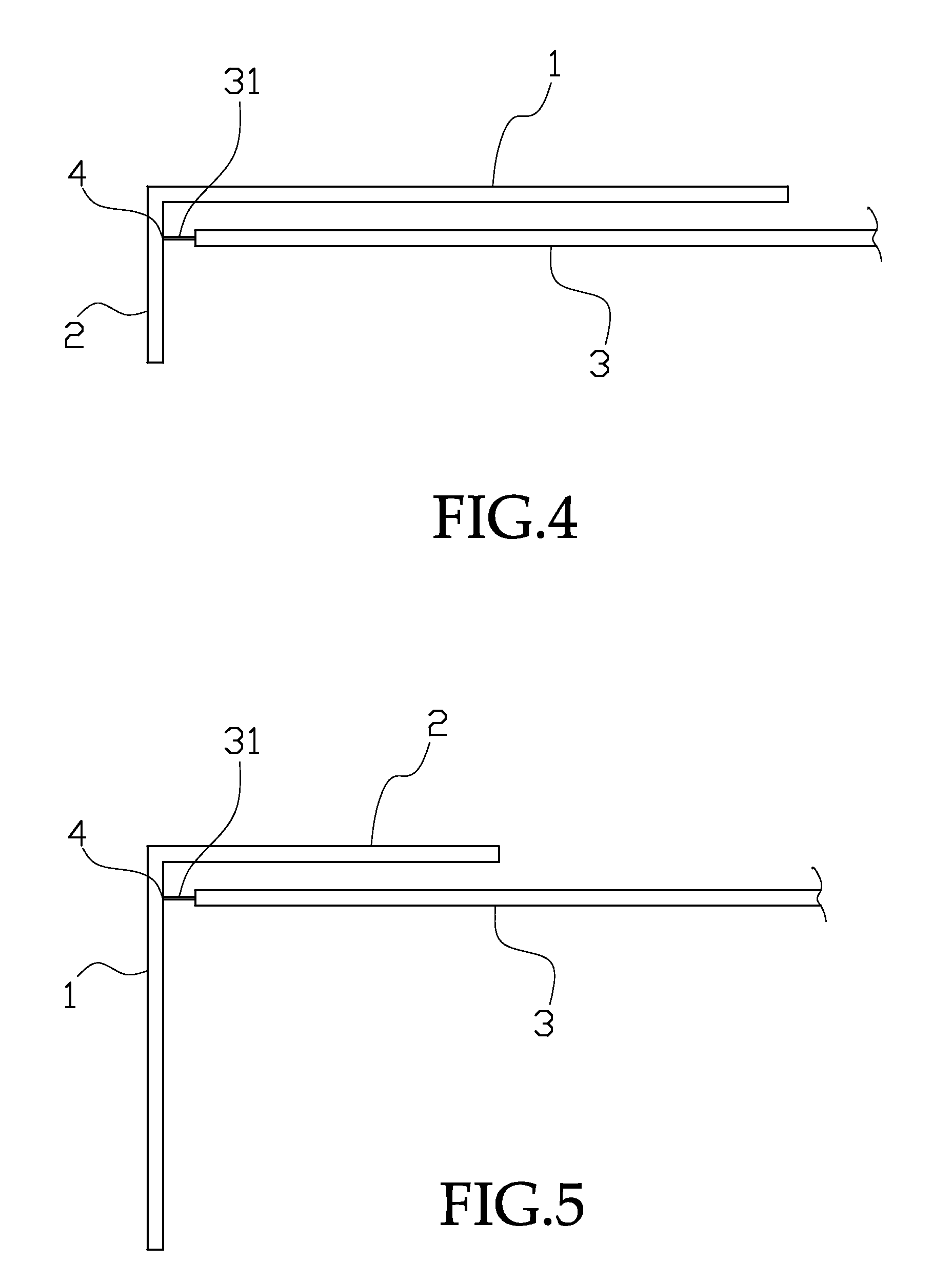
[0020]The low-frequency antenna path 1 and the high-frequency antenna path 2 are suitably connected as are shown in FIGS. 1-5; then the coaxial cable 3 is used as a signal transmitting cable to feed out signals.

[0021]In connecting of the present invention, a core line 31 for signal transmitting of the coaxial cable 3 is connected with a signal feed-in point 4 of the antenna, but a grounding line of the coaxial cable 3 is not connected with the anten...


PUM


Abstract

A broadband antenna applicable to a portable wireless electronic communication product, and especially suitable to be provided on the top or on two sides of a panel, it includes structurally a low-frequency antenna path, a high-frequency antenna path connected with the low-frequency antenna path, and a coaxial cable for feeding out a signal; the core line of the coaxial cable for signal transmission is connected with a signal feed-in point of the antenna, but a grounding line of the coaxial cable is not connected with the antenna to avoid making the coaxial cable a parasitic element of the antenna; the coaxial cable is arranged parallely to the low-frequency antenna path or the high-frequency antenna path, the grounding line of the coaxial cable is used to do perturbation against the transmission path of the antenna, thereby the antenna can get an effect of a broad bandwidth.

Description

BACKGROUND OF THE INVENTION[0001]1. Field of the Invention[0002]The present invention is related to a broadband antenna used for a portable wireless electronic communication product and provided on the top or on two sides of a panel; and especially to a broadband antenna of which a low-frequency antenna path is connected with a high-frequency antenna path, and of which a coaxial transmission cable is arranged parallely to the low-frequency antenna path or the high-frequency antenna path, the core line of the coaxial cable being connected with a feed-in point of the antenna but a grounding line of the coaxial cable being not connected with the antenna, in order that the antenna can get an effect of a broad bandwidth.[0003]2. Description of the Prior Art[0004]An early wireless transmission communication antenna unit is composed of a cylinder provided therein with a coil having a set length. Such a conventional coil antenna is stable and reliable in emitting and receiving signals, but ...

Claims


Application Information

Patent Timeline
Patent Type & Authority Applications(United States)
IPC IPC(8): H04H20/28H04H1/00
CPCH01Q5/371H01Q1/243
Inventor CHEN, I-FONG
Owner CHANT SINCERE
Why Eureka
Try Eureka