
System and method for multi-up inline testing of radio frequency identification (RFID) inlays

a radio frequency identification and tag device technology, applied in the field of multi-up inline testing of radio frequency identification (rfid) tag devices, can solve the problems of system failure to meet the requirements of the test system

Inactive Publication Date: 2008-05-01
SYMBOL TECH INC
View PDF8 Cites 28 Cited by
  • Summary
  • Abstract
  • Description
  • Claims
  • Application Information

AI Technical Summary

Problems solved by technology

However, test systems that can rapidly and reliably handle large volumes of tags are not readily available.
Current testing systems, which radiate test signals through the air, are extremely difficult to control and are reaching their limits in terms of the volume of tags that can be reliably tested.
Such systems can suffer from a variety of problems.
For example, systems using radiated test signals sometimes unintentionally read adjacent tags, and thus have difficulty identifying a specific “bad” tag from a group of tags.
Such systems may suffer from interference with the surrounding environment (e.g., interference with other radio frequency signals).
When multiple testing antennas are used to test multiple tags, such systems may suffer from cross-talk with the adjacent systems.

Method used


Image

  • System and method for multi-up inline testing of radio frequency identification (RFID) inlays
  • System and method for multi-up inline testing of radio frequency identification (RFID) inlays
  • System and method for multi-up inline testing of radio frequency identification (RFID) inlays

Examples


example embodiments

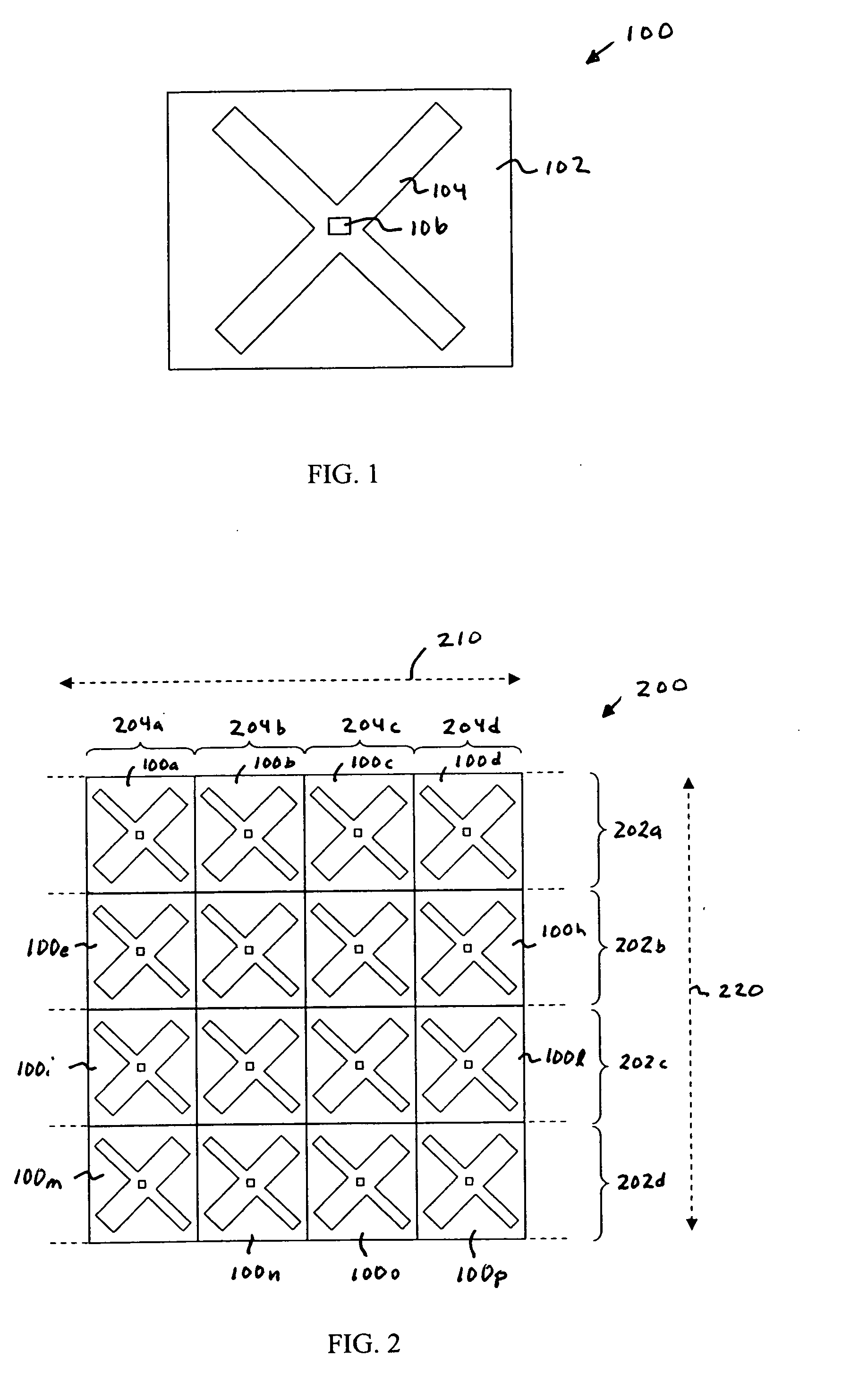
[0033]The present invention is applicable to any type of RFID tag. FIG. 1 shows a plan view of an example radio frequency identification (RFID) tag 100. Tag 100 includes a substrate 102, an antenna 104, and an integrated circuit (IC) 106. Antenna 104 is formed on a surface of substrate 102. Antenna 104 may include any number of one or more separate antennas. IC 106 includes one or more integrated circuit chips / dies, and can include other electronic circuitry. IC 106 is attached to substrate 102, and is coupled to antenna 104. IC 106 may be attached to substrate 102 in a recessed and / or non-recessed location. IC 106 controls operation of tag 100, and transmits signals to, and receives signals from RFID readers using antenna 104. Tag 100 may additionally include further elements, including an impedance matching network and / or other circuitry. The present invention is applicable to tag 100, and to other types of tags, including surface acoustic wave (SAW) type tags.

[0034]Embodiments de...


PUM


Abstract

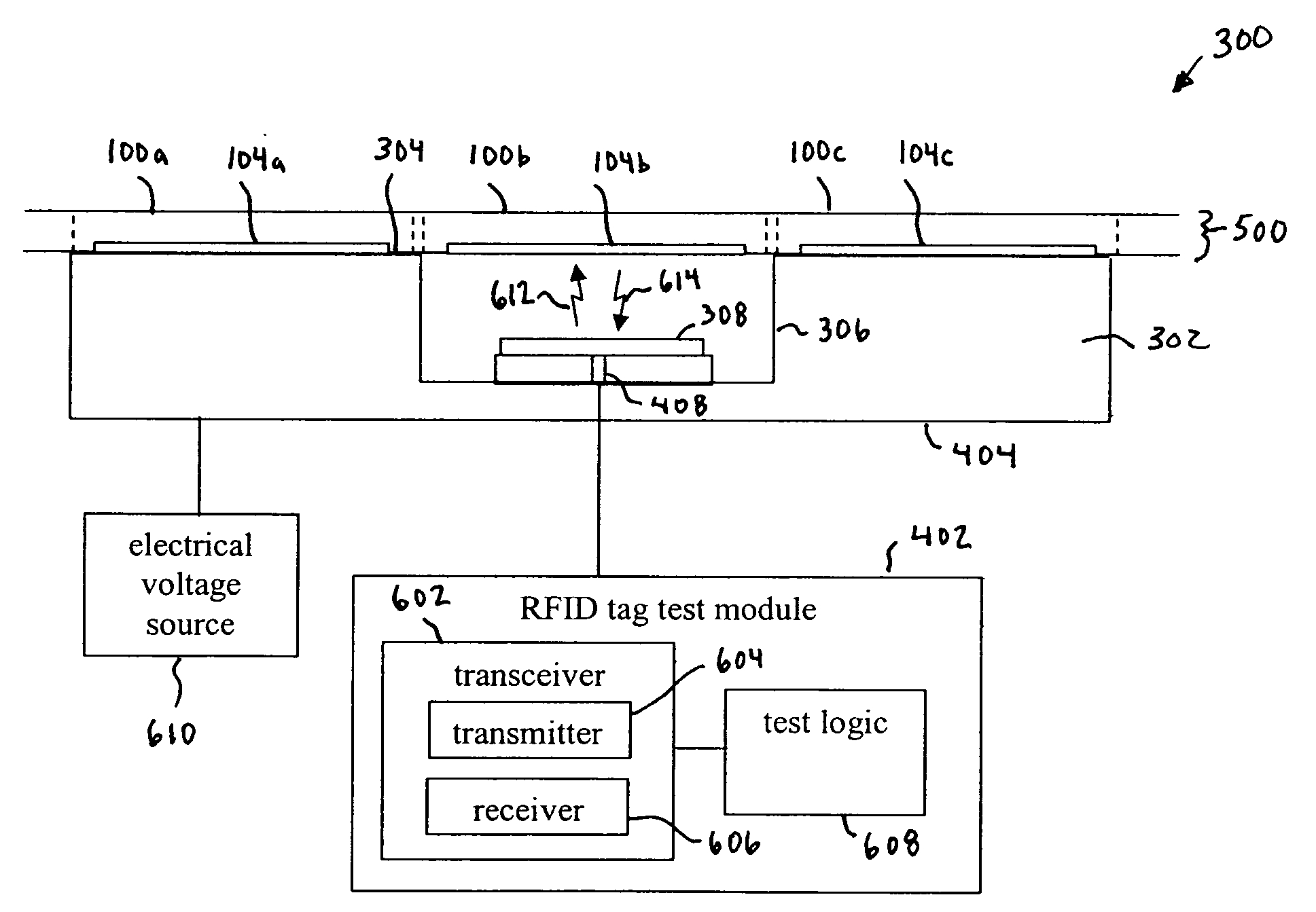
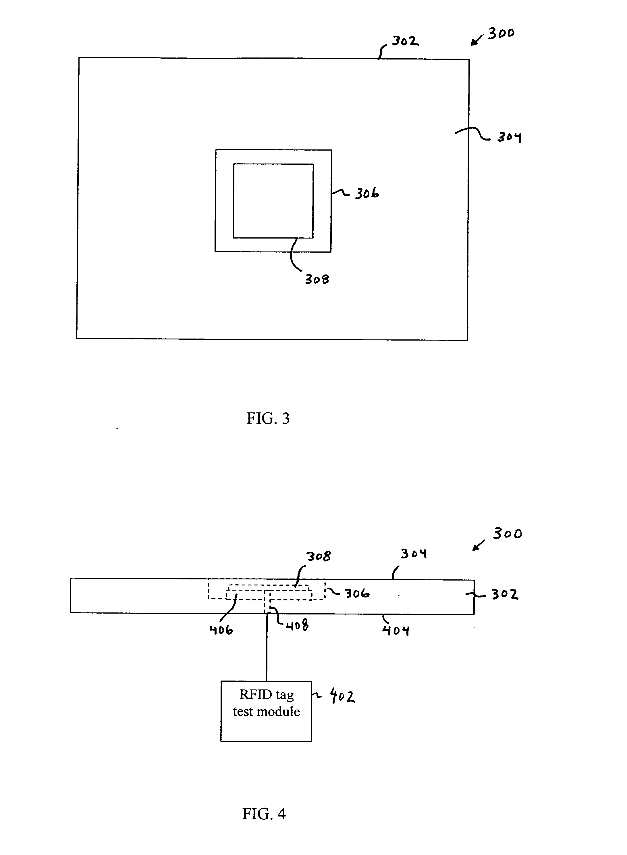
Methods, systems, and apparatuses for ways of testing tags are provided. In an aspect of the present invention, an antenna is mounted in a cavity of a surface. The antenna transmits a test signal, such as a radio frequency (RF) test signal, to the antenna of an adjacent tag, to test the adjacent tag. In aspects, multiple cavities having antennas may be arranged in various ways in the surface, such as in a “checkerboard pattern” (e.g., diagonally positioned from each other), to test multiple tags in a web of tags simultaneously. In another aspect, tags that are not being tested may be held at an electrical voltage, such as a ground voltage, to disable the tags from responding to the test signals of other tags. For example, in an aspect, a vacuum system may be used to hold tags in a web of tags to the surface to hold antennas of the tags at the electrical voltage.

Description

BACKGROUND OF THE INVENTION[0001]1. Field of the Invention[0002]The present invention relates to the testing of radio frequency identification (RFID) tag devices.[0003]2. Background Art[0004]Radio frequency identification (RFID) tags are electronic devices that may be affixed to items whose presence is to be detected and / or monitored. The presence of an RFID tag, and therefore the presence of the item to which the tag is affixed, may be checked and monitored by devices known as “readers.” Readers typically transmit radio frequency signals to which the tags respond. Each tag can store a unique identification number. The tags respond to the reader-transmitted signals by providing their identification number, bit-by-bit, so that they can be identified.[0005]Ideally, tags are tested for proper performance prior to being sold. Demand for RFID tags is estimated to be for over a billion tags a year. Having an accurate high-speed test system that can support such volume is extremely critica...

Claims


Application Information

Patent Timeline
Patent Type & Authority Applications(United States)
IPC IPC(8): G01R31/26H04Q5/22G08B13/14
CPCG01R31/2822G06K7/10465G06K7/0095G06K7/0008
Inventor NGUYEN, DANIELNARANJO, FRANCISCOSEIMS, GARYLAM, PETERREED, DAVIDLASALA, ANTHONY
Owner SYMBOL TECH INC
Learn More