DC-DC Converter and Its Controlling Method
- Summary
- Abstract
- Description
- Claims
- Application Information
AI Technical Summary
Benefits of technology
Problems solved by technology
Method used
Image
Examples
1st embodiment
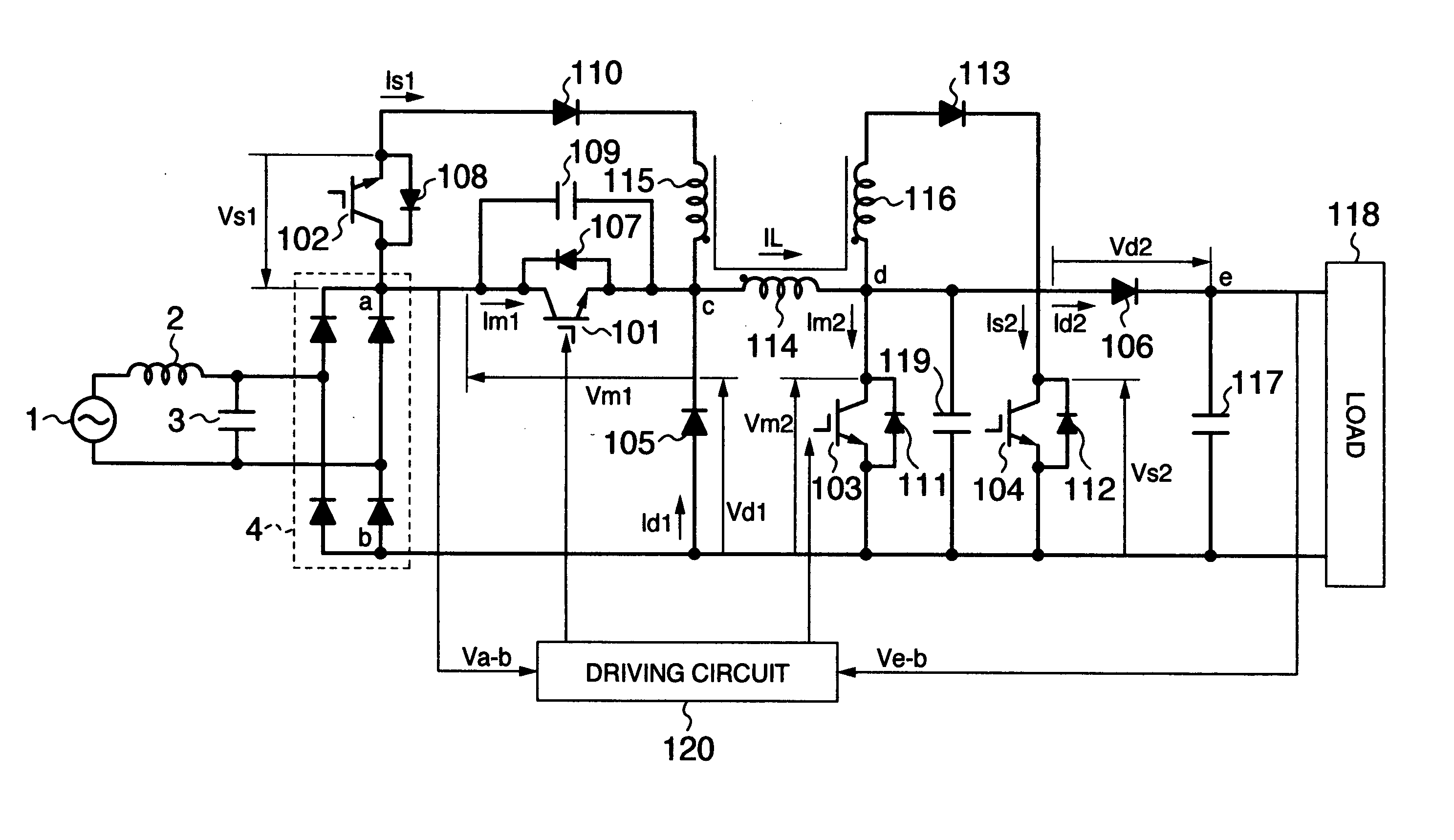
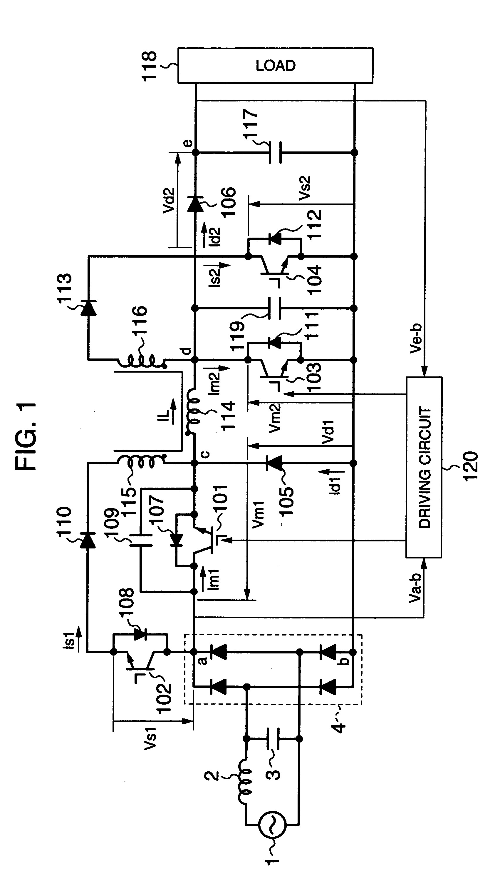
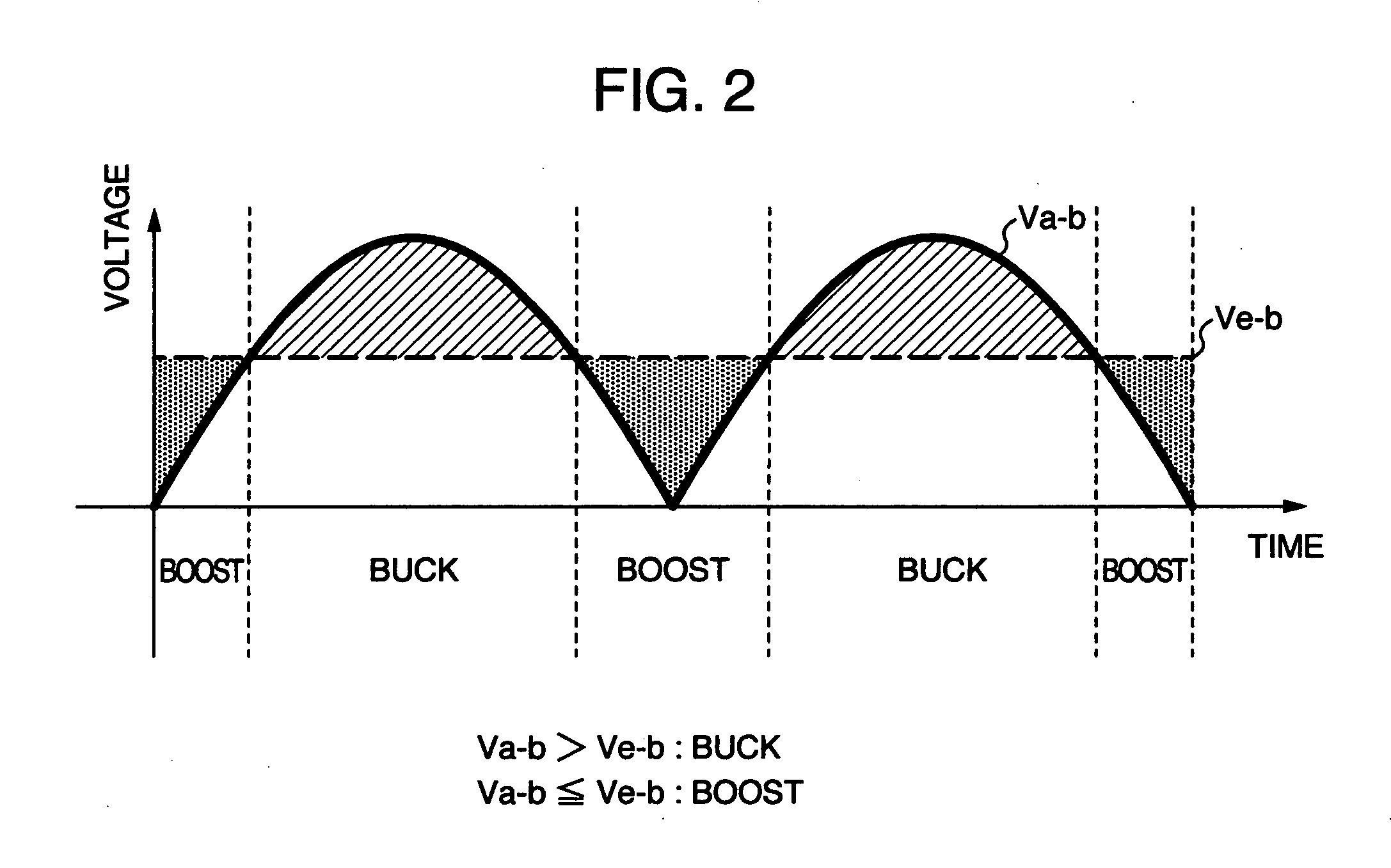
[0033] First, referring to FIG. 1 and FIG. 2, the explanation will be given below concerning a first embodiment of the present invention.
[0034]FIG. 1 is a configuration diagram of the main circuit of a unidirectional DC-DC converter according to the first embodiment of the present invention. The present embodiment is a unidirectional DC-DC converter of buck-boost type for allowing implementation of both a boost operation for outputting a voltage higher than an inputted voltage and a buck operation for outputting a voltage lower than the inputted voltage.
[0035] Explaining the main-circuit configuration in FIG. 1, a DC power-supply is configured with a commercial AC power-supply 1, a filter circuit including an inductor 2 and a capacitor 3, and a rectifier circuit 4. Namely, the entire AC voltage from the commercial AC power-supply 1 is rectified by the rectifier circuit 4 via the filter circuit including the inductor 2 and the capacitor 3, thereby being converted into a smooth DC v...
2nd embodiment
[0067] Next, referring to FIG. 7 and FIG. 8, the explanation will be given below concerning a second embodiment of the present invention.
[0068]FIG. 7 is a configuration diagram of the main circuit of a unidirectional DC-DC converter according to the second embodiment of the present invention. The present embodiment is a unidirectional DC-DC converter of buck-boost type for allowing implementation of both the boost operation for outputting a voltage higher than an inputted voltage and the buck operation for outputting a voltage lower than the inputted voltage.
[0069] In FIG. 8, the same reference numerals are affixed to the same configuration components as the ones illustrated in FIG. 1, and thus the overlapped explanation will be avoided.
[0070] The point in which the present embodiment differs from the first embodiment is a driving method for driving the main IGBT 101, i.e., the first main switching element. The configuration of this driving method is as follows: A point-in-time a...
3rd embodiment
[0075] Next, referring to FIG. 9 and FIG. 10, the explanation will be given below concerning a third embodiment of the present invention.
[0076]FIG. 9 is a configuration diagram of the main circuit of a unidirectional DC-DC converter according to the third embodiment of the present invention. The present embodiment is a unidirectional DC-DC converter of buck-boost type for allowing implementation of both the boost operation for outputting a voltage higher than an inputted voltage and the buck operation for outputting a voltage lower than the inputted voltage.
[0077] In FIG. 9, the same reference numerals are affixed to the same configuration components as the ones illustrated in FIG. 1, and thus the overlapped explanation will be avoided.
[0078] The point in which the present embodiment differs from the first embodiment is a driving method for driving the main IGBT 101, i.e., the first main switching element. The configuration of this driving method is as follows: A point-in-time is...
PUM
 Abstract
Description
Claims
Application Information
 - R&D
- Intellectual Property
- Life Sciences
- Materials
- Tech Scout
- Unparalleled Data Quality
- Higher Quality Content
- 60% Fewer Hallucinations
Browse by: Latest US Patents, China's latest patents, Technical Efficacy Thesaurus, Application Domain, Technology Topic, Popular Technical Reports.
© 2025 PatSnap. All rights reserved.Legal|Privacy policy|Modern Slavery Act Transparency Statement|Sitemap|About US| Contact US: help@patsnap.com


