
Bone fixation system

a bone fixation system and bone technology, applied in the field of bone fixation system, can solve the problems of inconvenient patient treatment, unfavorable patient treatment, and inability to fix the bone, so as to increase the number of configurations possible, prevent the dislocation of the bone plate element

Inactive Publication Date: 2008-04-24
WEINSTEIN ROBERT B
View PDF20 Cites 51 Cited by
  • Summary
  • Abstract
  • Description
  • Claims
  • Application Information

AI Technical Summary

Benefits of technology

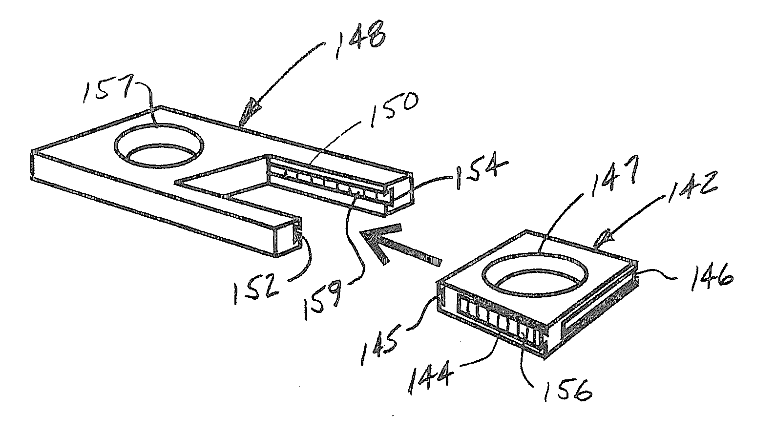
[0013]Embodiments of the invention also include a compression member configured to cooperate with at least one of the bone plate elements to provide a means not only for fixation of a fracture, but also to apply compression to the fracture as it heals. The compression member can be configured with a receiving portion to receive one or more of the bone plate elements therein. The receiving portion can be configured to cooperate with one or more of the connecting members on the bone plate element, and further, can be configured with a high-friction surface to help maintain compression and prevent dislocation of the bone plate element after it is disposed within the receiving portion.
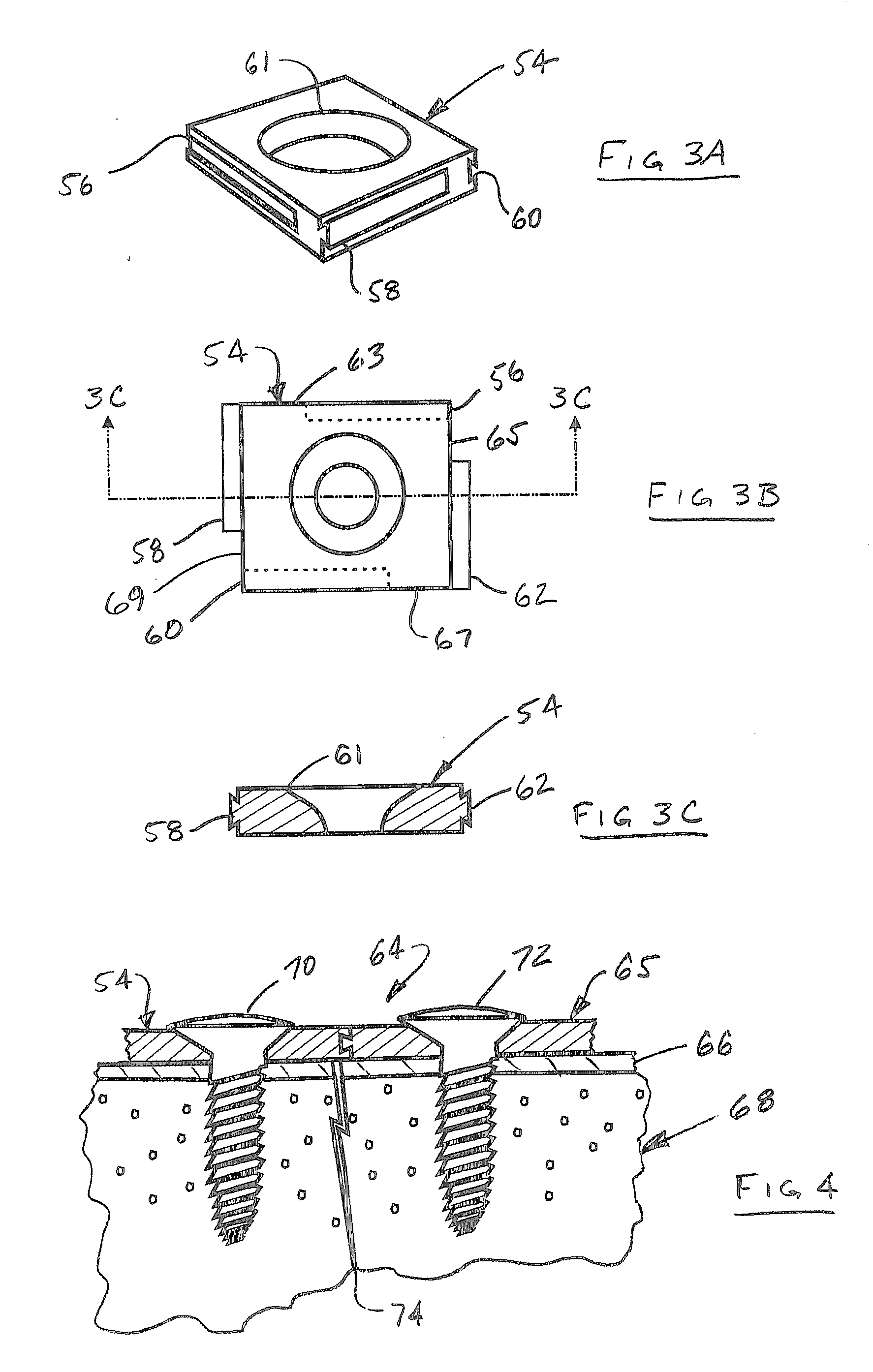
[0014]Bone plate elements in accordance with the invention may be configured as different geometric shapes, each having cooperating connecting members. In this way, for example, hexagonal bone plate elements can be connected to rectangular bone plate elements to further increase the number of configurations possible for the bone plate arrangements.

Problems solved by technology

Despite the usefulness of linear plates in some applications, the surgeon often encounters a situation where a using linear plate would result in suboptimal fixation of the bones.
For example, the plate may lie over a region of a bone defect where a corresponding bone screw has no bone to engage beneath the plate, which renders that particular plate hole useless.
Thicker plates commonly result in discomfort to the patient, and very often these plates require a secondary operation to remove them.
Cutting a plate for a specific need can result in weakness of a plate and exposed roughened metal surfaces that are more prone to fretting corrosion.
Specially formed or shaped plates, although sometimes available, are also not generally kept in large inventories due to the expense and relative infrequency of use.
Therefore, when there is a need for this type of specialty plating, or if inventory of a particular size plate is exhausted, it may not be available to the surgeon, potentially compromising the operation.
As an alternative to internal screws, external fixators are employed as a reliable means of creating direct axial compression across the fusion site; however, their use in the extremities is limited for elective fusion and reconstruction.
This is due to their cumbersome nature and relatively high potential for complications.

Method used


Image

  • Bone fixation system
  • Bone fixation system
  • Bone fixation system

Examples


Embodiment Construction

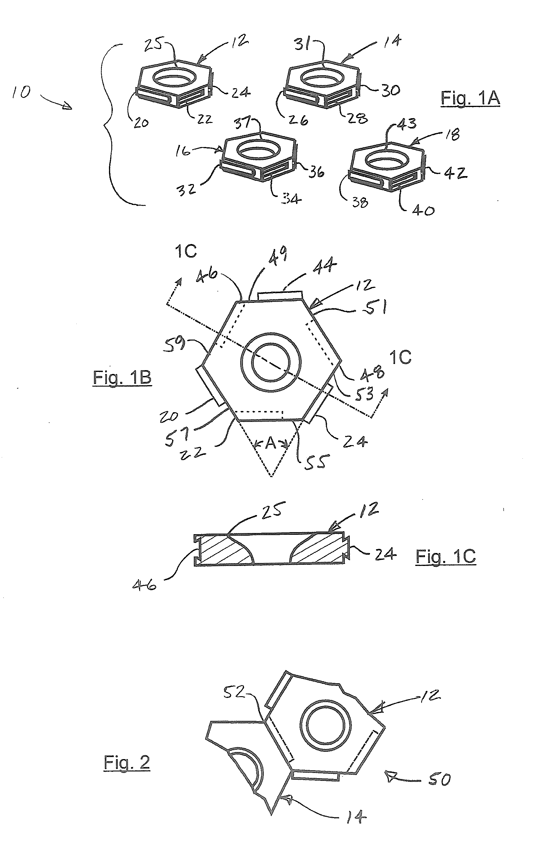
[0041]FIG. 1A shows a bone fixation system 10 in accordance with an embodiment of the present invention. The bone fixation system 10 includes a number of bone plate elements 12, 14, 16, 18. Each of the bone plate elements 12, 14, 16, 18 includes a number of connecting members that are configured to cooperate with other connecting members to selectively connect some or all of the bone plate elements 12, 14, 16, 18 to each other. For example, the bone plate element 12 includes connecting members 20, 22, 24. The connecting members 20, 24 are a first type of connecting member, and specifically, a male portion of a dovetail, having a generally triangular cross section. The connecting member 22 is a second type of connecting member, and specifically, a female portion of a dovetail, also having a generally triangular cross section, and configured to receive male dovetail portions, such as the connecting members 20, 24. The bone plate element 12 also includes an aperture 25 disposed thereth...


PUM


Abstract

A bone fixation system includes a plurality of bone plate elements, each of which includes a plurality of connecting members. At least one of the bone plate elements includes at least one of a first type of the connecting members, and at least one other of the bone plate elements includes at least one of a second type of the connecting members. Each of the at least one first type of connecting members is configured to cooperate with a respective one of the second type of connecting members to connect at least two of the bone plate elements together, thereby forming a bone plate arrangement. At least some of the bone plate elements have an aperture therethrough for receiving a fastener to affix the bone plate arrangement to a bone.

Description

CROSS-REFERENCE TO RELATED APPLICATIONS[0001]This application claims the benefit of U.S. provisional patent application Ser. No. 60 / 853,619 filed on 23 Oct. 2006, which is hereby incorporated herein by reference.BACKGROUND OF THE INVENTION[0002]1. Field of the Invention[0003]The present invention relates to a bone fixation system.[0004]2. Background Art[0005]Fixation of a bone with a plate is often performed using an internal device mounted directly to the bone adjacent a fracture, osteotomy, or arthrodesis. The plate is affixed to the bone with fasteners, usually bone screws, spaced along the length of the plate. Current plating systems generally employ a straight or linear plate of varied lengths. In some instances, specially configured or shaped plates are employed when a linear plate would not be appropriate. One example is a calcaneal perimeter plate, which has a shape similar to the normal contour of a calcaneus bone; however, it is useful only for reconstruction of the latera...

Claims


Application Information

Patent Timeline
IPC IPC(8): A61B17/58A61B17/00
CPCA61B17/8004A61B17/8061A61B17/8023
Inventor WEINSTEIN, ROBERT B.
Owner WEINSTEIN ROBERT B
Learn More