
Lighting Device

a technology of lighting device and led light, which is applied in the field of lighting device, can solve the problems of difficult implementation of lighting device, inability to meet the above-mentioned requirements simultaneously, and large amount of power consumed by lighting elements, and achieve the effect of tunable light intensity

Inactive Publication Date: 2008-04-24
VAISH HIMANGSHU RAI
View PDF18 Cites 47 Cited by
  • Summary
  • Abstract
  • Description
  • Claims
  • Application Information

AI Technical Summary

Benefits of technology

[0008] It is yet another object of the invention to provide a lighting device—that has tunable light intensity and a preset viewing angle.
[0009] It is yet a further object of the invention to provide a lighting device—that can detect partial failures within itself.
[0010] It is yet another object of the invention to provide a lighting source that can indicate failure and activate alarms before a complete failure takes place.
[0014] The light-source can be provided with a reflector for reflecting the light beam generated by the light-source. Motor(s) is / are used to rotate the generated light beam(s) by rotating either the light-source and / or, a reflector or, any such combination. The rotation speed of the motor is adjustable and may be varied according to the requirements. At different rotating speeds the light beam simulates either a flashing or a continuous beam of light. Motor(s) and lighting-source(s) are covered in a covering. This covering can be a polycarbonate, it provides rigidity and water proofing to the device.

Problems solved by technology

The existing technology for lighting devices—mainly depends on the lighting elements—like bulb or halogen etc., however, these lighting elements consume a large amount of power and are very expensive to maintain.
However, the implementation of a lighting device—using LEDs for the aforesaid task is difficult due to various constraints associated with the LEDs, like directional nature of light, and the demanding specifications and expectations from the lighting devices.
The existing technologies using LEDs are not able to meet the above-mentioned requirements simultaneously.
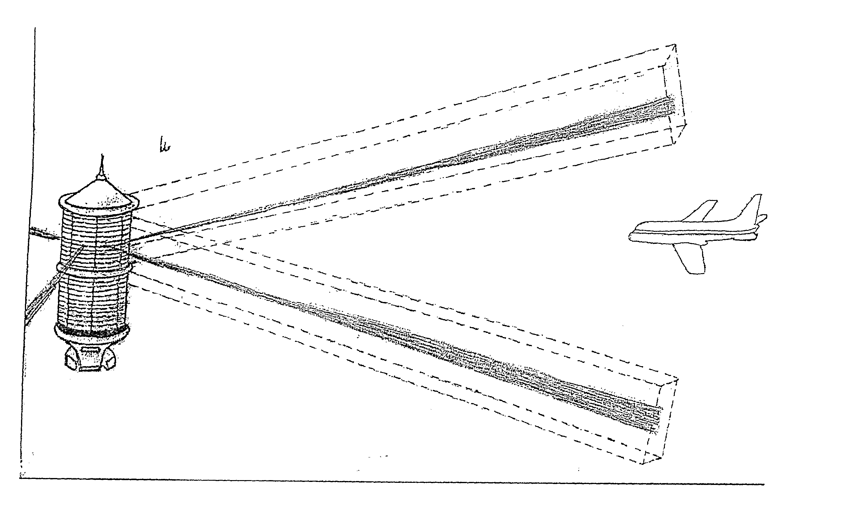
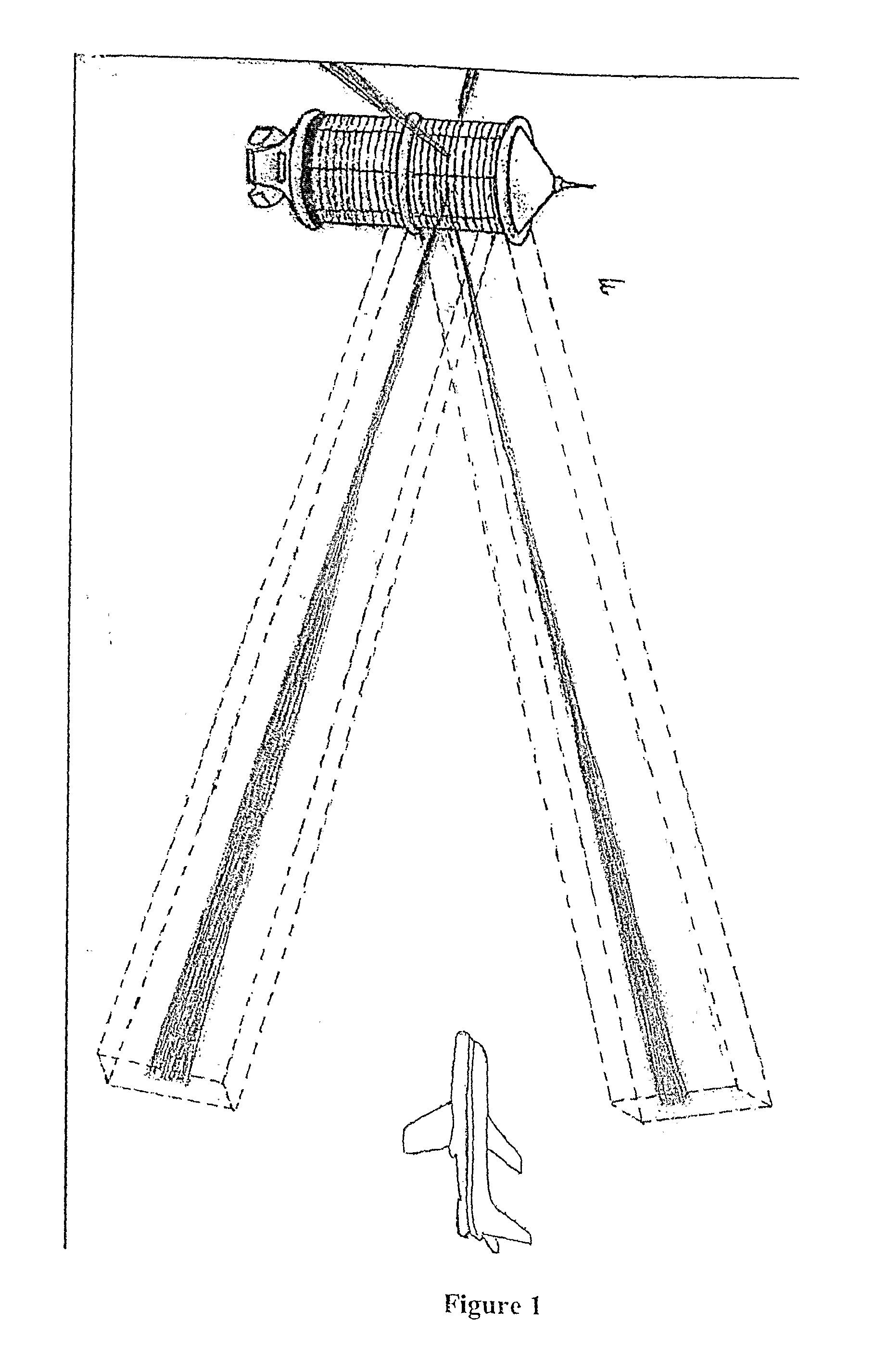
However, the light sources of this type not only require large number of LEDs to be placed which not only reduces the reliability of the circuitry but also they do not meet the requirement of uniform visibility from all the directions as it is apparent from—FIG. 1, which shows a large dark area into which an aircraft is flying.
Furthermore, the light intensity desired at long distances is also a subject of concern.
In such lighting devices due to the light output required, a large number of LEDs have to be used, which not only consume more power but also increases the weight of the device and still does not meet the specifications for such devices in terms of intensity, viewing angle and all round visibility.

Method used


Image

  • Lighting Device
  • Lighting Device
  • Lighting Device

Examples


Embodiment Construction

[0025] A further understanding of the present invention may be obtained with reference to the following description taken in conjunction with the accompanying drawings. However, the embodiments used for describing the invention are illustrative only and no way limiting scope of the invention. A person skilled in the art will appreciate that many more embodiments of the invention are possible without deviating from the basic concept of the invention any such embodiment will fall under the scope of the invention and is a subject matter of protection.

[0026] In the following description light-source is one or more lighting elements mounted on a metal plate where lighting elements are either LED(s) and / or laser diodes and / or quantum dots.

[0027] Lighting device defines an assembly of light-source coupled with a motor and both light-source and motor are controlled by a controller.

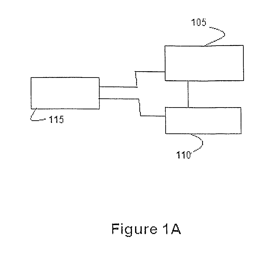
[0028]FIG. 1A depicts a block diagram of one embodiment of the present invention. Here, block 105 represent ...


PUM


Abstract

A lighting device comprising, one or more semiconductor light-sources for generating a light beam, at least a motor for rotating said light beam, and a controller for controlling speed of rotation of the motor and intensity of the light-source and monitoring the operating conditions, detecting failures of the lighting device and / or, any of its components and setting off alarms which could be audio / visual and / or, radio or, telecom equipment using land and / or, air and / or, satellite links. The light beam generated by the light-sources is rotated. The light assembly broadly finds application in aviation industry, obstacle beacons, lighthouses and entertainment industry.

Description

FIELD OF THE INVENTION [0001] The invention generally relates to a lighting device, more specifically to a lighting device for providing isometric rotating light beam of a high intensity from semiconductor lighting elements, like LEDs, whose light emission is directional in nature. that can be used in aviation industry, obstacle beacons etc., still more precisely the present invention relates to a semiconductor lighting device with capabilities of detecting failures in the device. BACKGROUND OF THE INVENTION [0002] In many situations there is a need for providing a light beam, which may be flashing and can be viewed from—many or all directions. For example, in aviation industry the visibility of the lighting—devices placed on top of a high rising obstacle is expected to be independent of—direction of observation. This is highly desirable to protect huge loss of life and property. Similarly lighthouses, buoys, etc. provide signals to ships in all directions and stages in auditoriums ...

Claims


Application Information

Patent Timeline
IPC IPC(8): F21V14/02F21V14/04
CPCF21S10/06F21V14/02F21V29/89F21W2111/04F21V29/20F21V14/04F21V19/001
Inventor VAISH, HIMANGSHU RAI
Owner VAISH HIMANGSHU RAI
Learn More