
Video traffic monitoring and signaling apparatus

a traffic monitoring and signaling technology, applied in the field of video traffic monitoring and signaling apparatus, can solve the problems of inductive loop mechanism failure, and cost of installation of video monitoring system, and achieve the effect of easy installation or retrofi

Active Publication Date: 2008-04-17
COGNEX CORP
View PDF7 Cites 21 Cited by
  • Summary
  • Abstract
  • Description
  • Claims
  • Application Information

AI Technical Summary

Benefits of technology

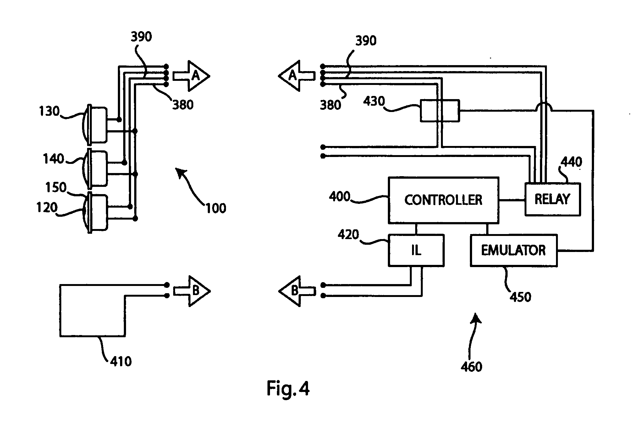
[0011] The system of the present invention provides an integrated system for traffic signaling and monitoring that is easy to install or retrofit using commonly used wiring and enclosures. In accordance with an illustrative embodiment, one or more lamps in a traffic signal head may be modified to include an embedded video monitoring system. An illustrative embedded video monitoring system including an image sensor, an image processor and a communications module, all installed behind the signal lamp itself. The signal lamp illustratively comprises of an array of light-emitting diodes (LEDs) that are physically arranged around a small circular area in the center that is left open so that the image sensor has a clear and unobstructed view of the intersection. The video monitoring systems analyzes the scene and then communicates its results to the control module by any of a variety of methods, including via frequency shift keying modulation over the power line. The control module then causes appropriate changes in the illumination of the lamps, i.e., to invoke a change in the traffic light status, e.g., from Red to Green, etc.

Problems solved by technology

Inductive loop mechanisms are expensive to install, since the roadway surface must be cut, and wire conductors must be inserted into the roadway surface, and routed to the traffic signal control box.
The inductive loop mechanisms are prone to failure, and, in the event of such a failure, the controller must resort to a default mode in which it cycles based on a timer.
These video monitoring systems are costly to install due to the additional equipment, installation and the additional wiring and power requirements.

Method used


Image

  • Video traffic monitoring and signaling apparatus
  • Video traffic monitoring and signaling apparatus
  • Video traffic monitoring and signaling apparatus

Examples


Embodiment Construction

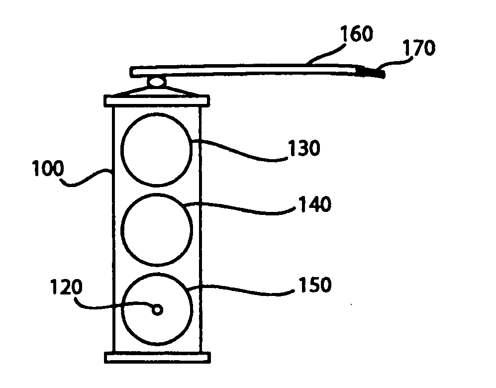
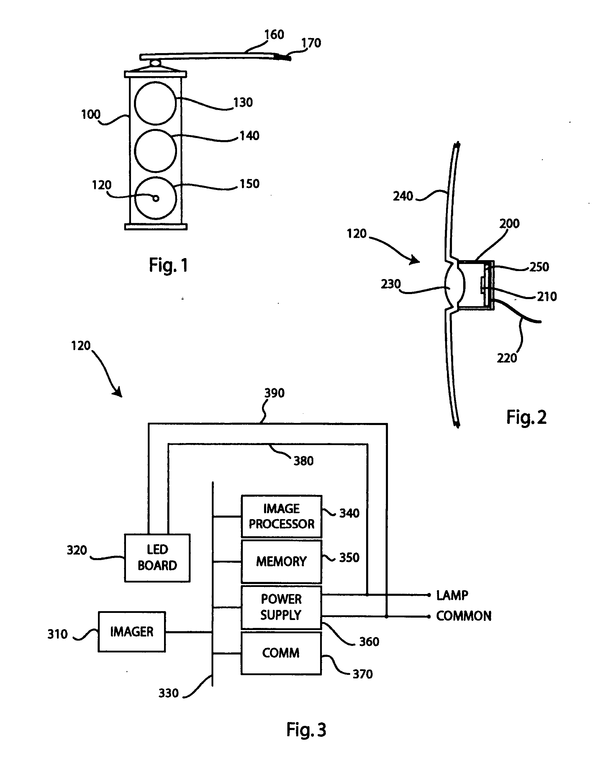
[0018]FIG. 1 depicts a video traffic monitoring and signaling apparatus according to an illustrative embodiment of the present invention. A traffic signal head 100 is shown suspended from a support 160, above an intersection. The signal head 100 is shown in a typical configuration with a red lamp 130, a yellow lamp 140 and a green lamp 150. The green lamp 150 is shown with an embedded video traffic monitor 120. A wiring harness 170, shown in cut-away, includes at least one wire for each lamp and a common neutral wire.

[0019] The embedded video monitoring system 120 can be installed in any of the signal lamps in the signal head 100. However, to minimize blooming effects of signaling illumination, it may be preferred that the embedded system 120 be installed in the green lamp, since the vehicle detection is most critical during the red illumination cycle for the detected traffic lane. One skilled in the art will appreciate that alternate modes of operation may warrant the installation...


PUM


Abstract

A traffic signal head having a signal lamp or signal ball with an embedded video monitoring system can be provided to perform vehicle detection to inform an intelligent traffic control system. Video monitoring of traffic lanes facing the signal head can be analyzed by such a system to emulate inductive loop signals that are input signals to traffic control systems.

Description

CROSS-REFERENCE TO RELATED APPLICATIONS [0001] The present application claims the benefit of U.S. Provisional Patent Application Ser. No. 60 / 786,166, which was filed on Mar. 27, 2006, by David Schatz and Robert Shillman for a VIDEO TRAFFIC MONITORING AND SIGNALING APPARATUS and is hereby incorporated by reference.BACKGROUND OF THE INVENTION [0002] 1. Field of the Invention [0003] The present invention relates generally to the application of vision monitoring in traffic control systems, and specifically toward a system having a video monitoring system integrated within a traffic signal lamp. [0004] 2. Background Information [0005] Efficient and effective traffic signaling systems are essential to meet the reliance on vehicular transportation that growing urban centers demand. Traffic signaling systems is are effective when they accurately detect vehicle queues at intersections, and control traffic signals in response to the queues while maintaining vehicular throughput on the main ro...

Claims


Application Information

Patent Timeline
Patent Type & Authority Applications(United States)
IPC IPC(8): G08G1/00
CPCG08G1/0175G08G1/095G08G1/08Y10S362/80
Inventor SHILLMAN, ROBERTSCHATZ, DAVID
Owner COGNEX CORP
Learn More