
Paper feeder

Active Publication Date: 2008-04-17
LITE ON TECH CORP
View PDF9 Cites 6 Cited by
  • Summary
  • Abstract
  • Description
  • Claims
  • Application Information

AI Technical Summary

Benefits of technology

[0014]In view of the above problems, the present invention provides a paper feeder, which eliminates the limitations or disadvantages in the prior art that the components are too complicated and difficult to assemble, and that the assembled components occupy too much space.
[0016]The effect of the present invention is simplifying the assembling procedure of the paper feeder, reducing the required space, and improving the lifetime.
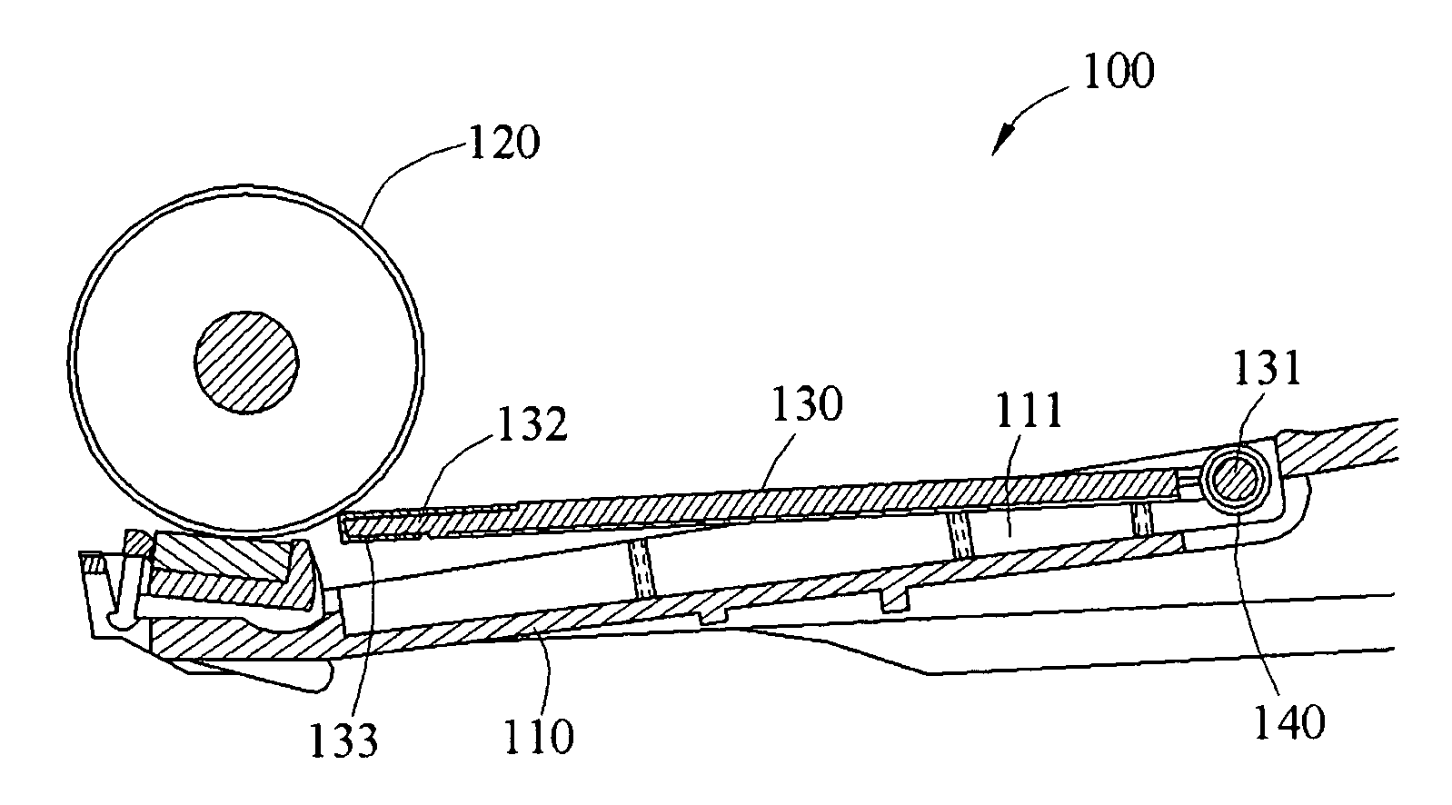
[0017]The paper feeder only comprises a base, a roller, a holder, and a torsional element only, so the complexity in assembling and the time for assembling is reduced significantly. Moreover, as the torsion output of the torsional element does not change much, even if the assembly tolerance occurs in the assembling, the torsion output of the torsional element is still controllable. Thus, the stability of picking up and feeding the paper for the paper feeder is improved.
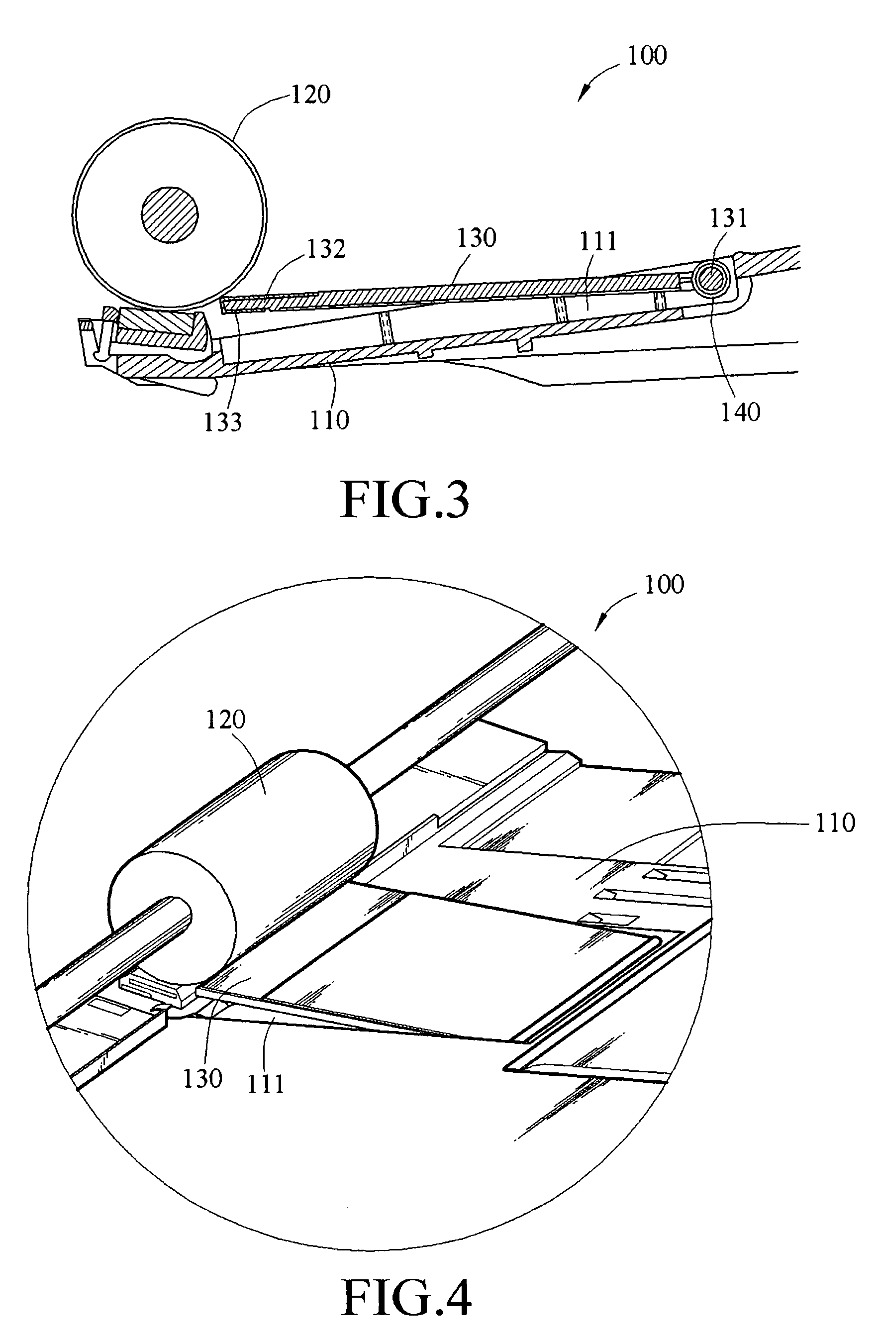
[0018]Furthermore, an accommodation portion is recessed on the base to accommodate the holder and the torsional element, and the accommodation space of the accommodation portion allows the holder to swing inside but not to be exposed outside the accommodation portion. Thus, the volume of the assembled paper feeder is reduced significantly, which satisfies the requirements of being light and simple in the design.
[0019]In addition, the holder is fabricated with a plastic flat plate. Thus, the material cost of the holder is reduced, and the weight is low. Moreover, the movable end of the holder is covered by a metal sheet, so the frictional force between the roller and the holder is reduced when there is no paper, which prevents additional abrasion loss of the roller, and increases the lifetime of the roller. When the roller picks up and feeds the paper, the frictional force between the paper and the holder is also reduced, such that the roller drives the paper smoothly.

Problems solved by technology

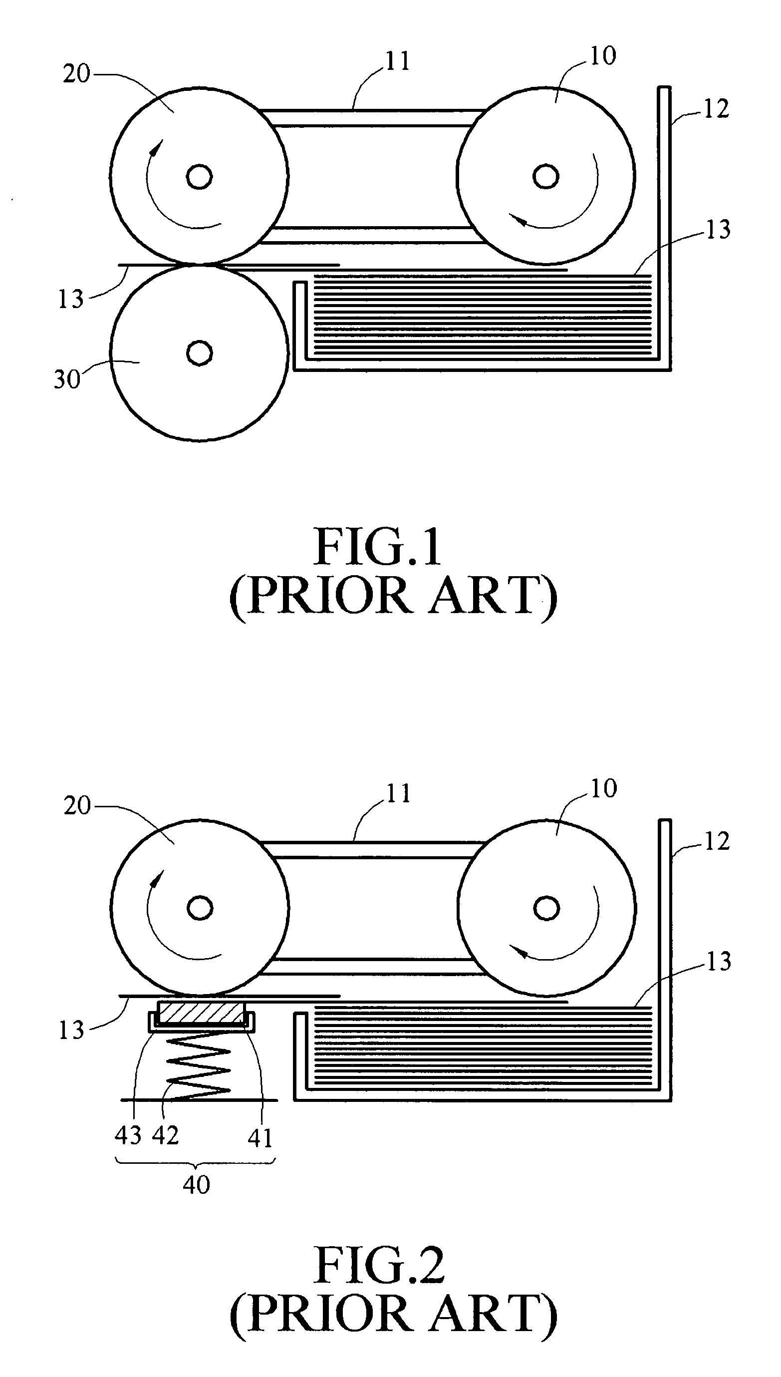
Therefore, the assembling is complicated, and the assembled components occupy too much space.

Method used


Image

  • Paper feeder
  • Paper feeder
  • Paper feeder

Examples


Embodiment Construction

[0028]To make the object, structure, features and function of the present invention more understandable, the present invention is illustrated below in detail with reference to the embodiments.

[0029]The paper feeder according to the disclosure of the present invention is applicable to devices with paper pickup and feed functions, such as faxes, printers, copiers, multi-functional peripherals (MFP), or scanners. In the detailed illustration of the present invention below, an MFP is used as a preferred embodiment of the present invention. However, the accompanying drawings are for reference and illustration only, but not intended to limit the present invention.

[0030]Referring to FIG. 3, a paper feeder 100 according to an embodiment of the present invention includes a base 110, a roller 120, a holder 130, and a torsional element 140.

[0031]The base 110 is disposed at an inlet of a paper feed track of the MFP. The roller 120 is disposed adjacent to the base 110, and is used to drive a pap...


PUM


Abstract

A paper feeder includes a base, a roller adjacent to the base, a holder for holding a paper, and a torsional element. The holder has a pivot end and a movable end, wherein the pivot end is pivoted to the base. The torsional element is disposed at a position where the holder is pivoted to the base, and provides torsion to move the movable end of the holder to be pressed against the roller, such that a front edge of the paper is raised to be in contact with the roller. As the roller rotates, the paper is fed into a paper feed track by a frictional force.

Description

CROSS-REFERENCE TO RELATED APPLICATIONS[0001]This non-provisional application claims priority under 35 U.S.C. § 119(a) on Patent Application No(s). 095218133 filed in Taiwan, R.O.C. on Oct. 13, 2006, the entire contents of which are hereby incorporated by reference.BACKGROUND OF THE INVENTION[0002]1. Field of Invention[0003]The present invention relates to a paper feeder, and more particularly to a paper feeder that reduces the occupied space and simplifies the assembling procedure.[0004]2. Related Art[0005]Various types of printing and output devices, such as printers, scanners, copiers and multi-functional peripherals (MFPs), are now available in the market. In each of these devices, two rubber rollers, including a pickup roller and a feed roller, are used to pickup and feed papers. The paper is firstly picked up from a paper tray by the pickup roller, and then is fed by the feed roller to perform the prearranged task, and finally is conveyed outside the device. The power for the ...

Claims


Application Information

Patent Timeline
IPC IPC(8): B65H1/08
CPCB65H1/12B65H2405/1117B65H2402/545B65H2402/54
Inventor LIU, JEN-CHIEHLIU, CHUN-LIANG
Owner LITE ON TECH CORP
Learn More