
Methods and apparatuses for operating devices with solar power

a technology for operating devices and solar energy, applied in the field of electronic devices, can solve the problems of difficult to track the solar power drawn from the solar cells to maintain a relatively stable solar power output, and oftentimes not having access to conventional ac outlets

Active Publication Date: 2008-04-10
APPLE INC
View PDF8 Cites 45 Cited by
  • Summary
  • Abstract
  • Description
  • Claims
  • Application Information

AI Technical Summary

Benefits of technology

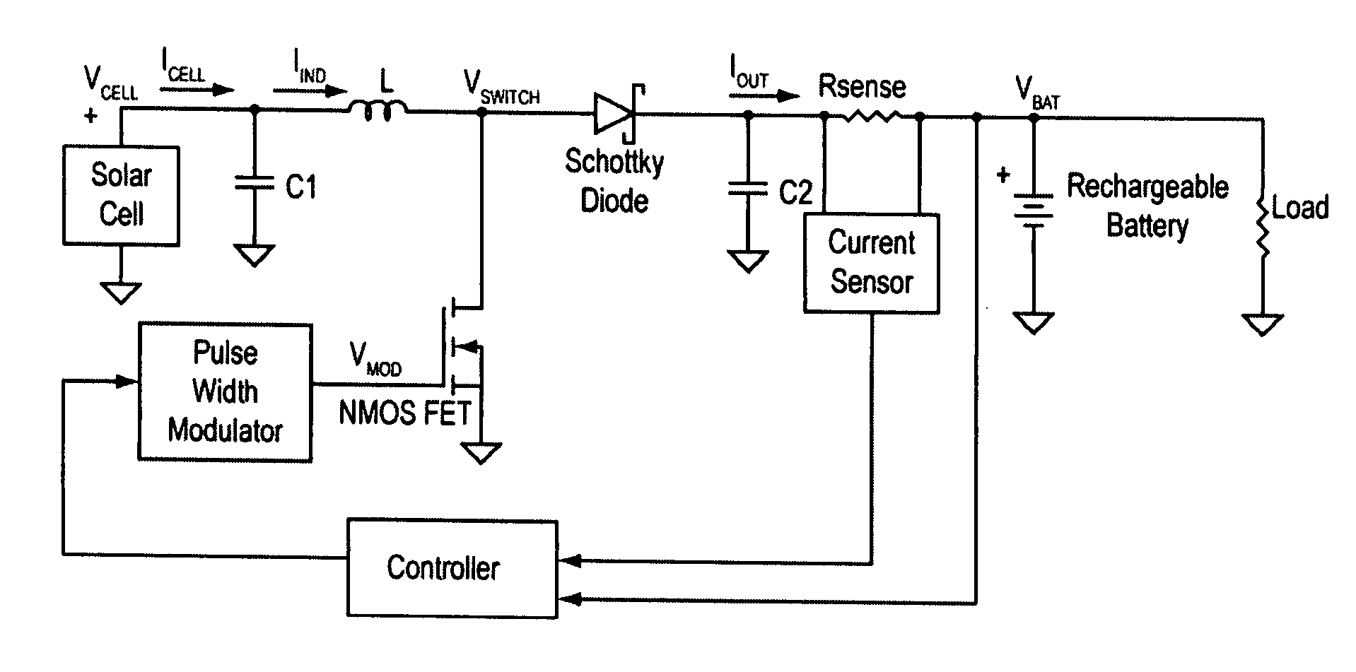
[0010]Techniques for operating devices with solar power are described herein. In one aspect of the invention, apparatus for operating a portable electronic device with solar power includes, but is not limited to, a voltage converter and a controller coupled to the voltage converter. The voltage converter includes an input capable of being coupled to a solar power source and an output capable of being coupled to an electronic load, such as, for exa

Problems solved by technology

However, mobile users who are in remote locations oftentimes do not have access to conventional AC outlets.
As a result, they oftentimes have no way of recharging the batteries of their handheld computing devices.
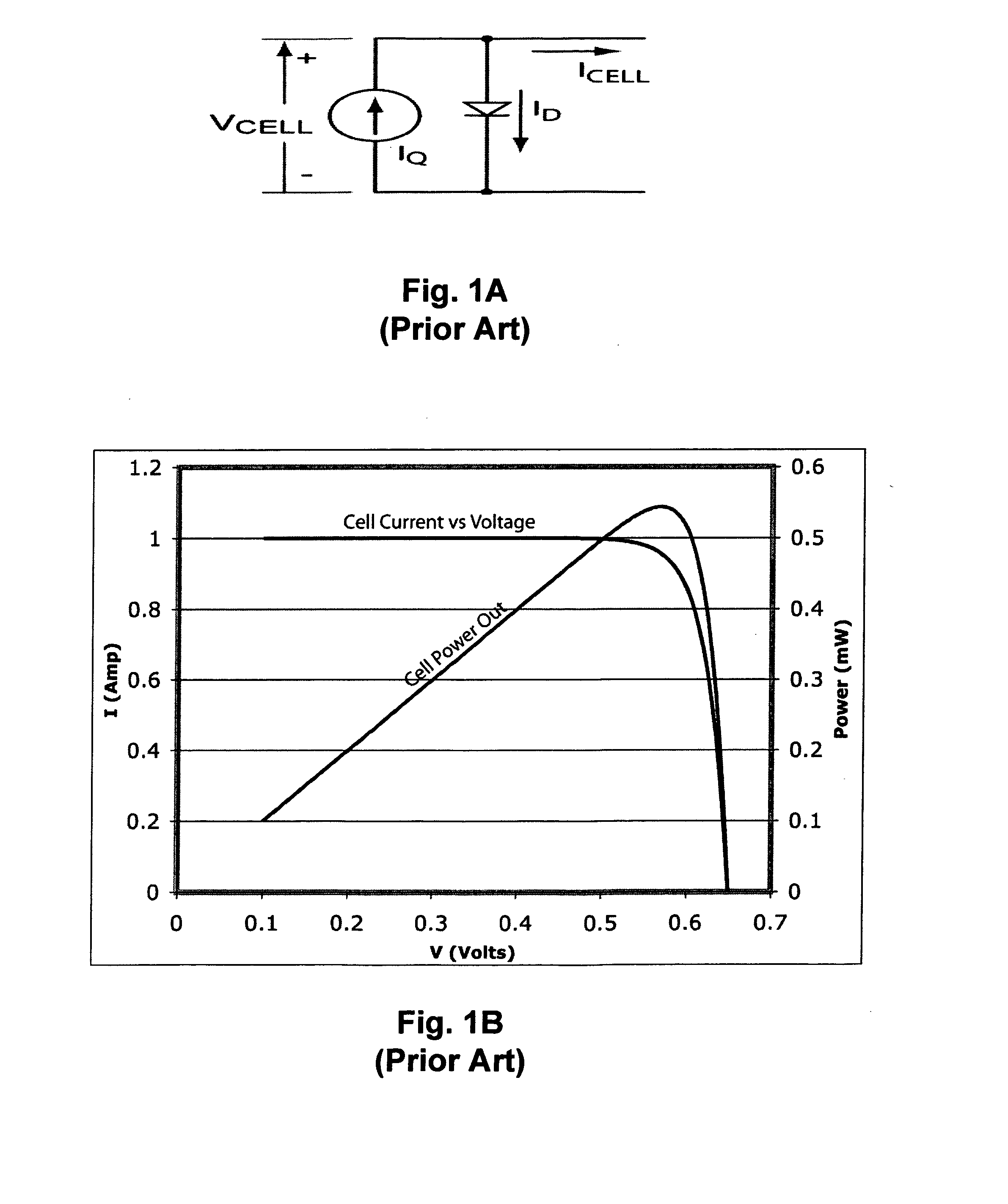
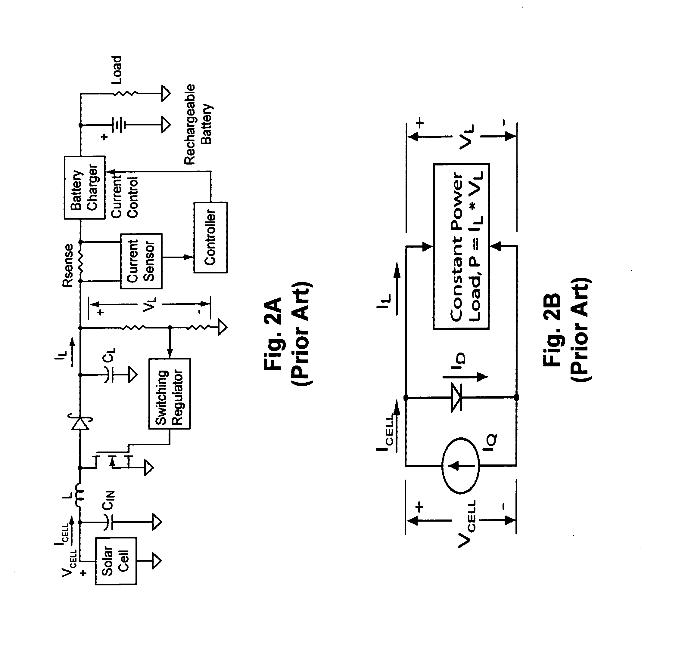
However, given the characteristics of the solar cells that provide solar power, it is relatively difficult to track the solar power drawn from the solar cells to maintain relatively stable solar power output.
The 600 mW load is always unstable because there is no intercept with the cell V-I curve.
These loads are unstable at Intercept A. With the 600 mW load the load will continue to demand current that the cell cannot supply so the cell will go into constant current mode and the cell voltage will go down.
However, such a device does not normally include other power sources to charge the battery.
Sometimes the solar power source or AC outlet may not be conveniently available.
In such circumstances, a device limited to one charging method may not function properly.

Method used


Image

  • Methods and apparatuses for operating devices with solar power
  • Methods and apparatuses for operating devices with solar power
  • Methods and apparatuses for operating devices with solar power

Examples


Embodiment Construction

[0026]In the following description, numerous details are set forth to provide a more thorough explanation of embodiments of the present invention. It will be apparent, however, to one skilled in the art, that embodiments of the present invention may be practiced without these specific details. In other instances, well-known structures and devices are shown in block diagram form, rather than in detail, in order to avoid obscuring embodiments of the present invention.

[0027]Reference in the specification to “one embodiment” or “an embodiment” means that a particular feature, structure, or characteristic described in connection with the embodiment is included in at least one embodiment of the invention. The appearances of the phrase “in one embodiment” in various places in the specification do not necessarily all refer to the same embodiment.

Techniques for Operating Devices with Solar Power

[0028]According to certain embodiments of the invention, an amount of power drawn at the point of ...


PUM


Abstract

Solar power tracking techniques are described herein. In one aspect of the invention, a solar power tracking apparatus includes, but is not limited to, a voltage converter and a controller coupled to the voltage converter. The voltage converter includes an input capable of being coupled to a solar power source and an output capable of being coupled to an electronic load, such as, for example, a portable electronic device. The voltage converter is configured to monitor or detect an amount of power drawn by the electronic load at the output of the voltage converter. In response to the monitored power drawn, the controller is configured to control the voltage converter to reduce amount of power to be drawn subsequently if the monitored amount of power exceeds a predetermined threshold. As a result, the output voltage from the solar power source is maintained within a predetermined range. Other methods and apparatuses are also described.

Description

FIELD OF THE INVENTION[0001]The present invention relates generally to electronic devices. More particularly, this invention relates to operating portable electronic devices with solar power.BACKGROUND[0002]Handheld computing devices typically use standard battery chemistries including ni-cad, lithium-ion, and nickel-metal hydride. In order to recharge these batteries, operators may use standard recharging options such as, for example, conventional AC (alternating current) outlets. However, mobile users who are in remote locations oftentimes do not have access to conventional AC outlets. As a result, they oftentimes have no way of recharging the batteries of their handheld computing devices.[0003]Recently, solar power has been used to power up a handheld device. As demands for the power of the handheld computing devices increase, it becomes more important to provide stable power to the devices. However, given the characteristics of the solar cells that provide solar power, it is rel...

Claims


Application Information

Patent Timeline
IPC IPC(8): H02J3/32
CPCH02J7/35Y02E10/56
Inventor SANDER, WENDELL B.WARREN, DANIEL A.LEIBA, AARON
Owner APPLE INC
Learn More