
Multi-tooth pawl type gearing mechanism

a gearing mechanism and multi-tooth technology, applied in the direction of clutches, friction clutches, freewheel clutches, etc., can solve the problems of limited engagement time, limited success of attempts, and drawback relating to engagement time, so as to facilitate the placement of cassette bodies and facilitate the placement of them. , the effect of convenient placemen

Inactive Publication Date: 2008-04-10
TURNAMICS
View PDF36 Cites 22 Cited by
  • Summary
  • Abstract
  • Description
  • Claims
  • Application Information

AI Technical Summary

Benefits of technology

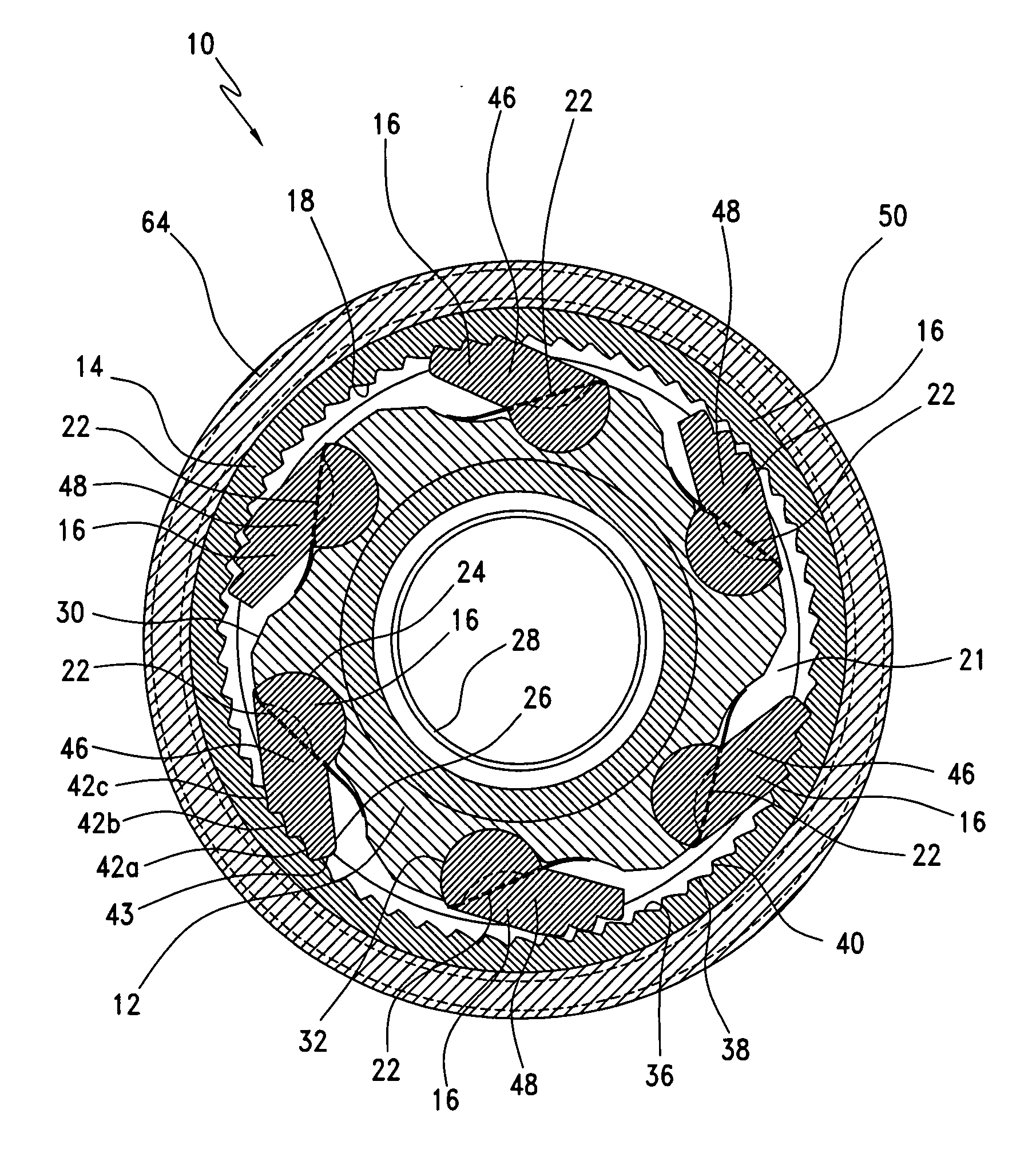
[0013] It is a further object of the present invention to provide a gearing mechanism wherein the geometry of the teeth on the pawl is designed so that when in free rotation only a tooth furthest from a tip of the pawl and closest to a point of rotation for the pawl interacts with the gear ring to reduce wear on the rest of the teeth.
[0015] It is also a further object of the present invention to provide a gearing mechanism wherein a leading edge of the gear ring is angled in a manner facilitating placement of the cassette body and pawls into the gear ring.
[0018] It is also an object of the present invention to provide a gearing mechanism wherein each pawl includes milled portions, the spring engaging an upper surface of the milled portions and acting to rotate the pawl and hold it down into a rotor member recess of the inner rotor member of the cassette body at a particular angle to facilitate ease of placement into recesses formed along the inner surface of the gear ring.
[0019] It is still another object of the present invention to provide a gearing mechanism wherein the milled portions on each pawl are shaped and dimensioned to maintain the pawl in a particular position and angle, and keep it from biasing too far toward the gear ring to facilitate an easier placement of the cassette body and pawls into the inner surface of the gear ring where the pawls are pushed down for assembly.
[0027] It is also an object of the present invention to provide a gearing mechanism wherein each recess includes an angularly oriented long first wall and a short second wall, the second wall being oriented such that teeth on the second end of the pawl seat within the recesses and abut the second wall in a manner preventing further rotation of the gear ring relative to the pawl when the inner rotor member is rotated in the first direction, and this configuration allows the teeth of the pawl to slide up and over the long first wall of each recess when the gear ring is rotated in the second direction opposite the first direction.

Problems solved by technology

The primary drawback relates to the engagement time.
In particular, engagement time is limited by the number of teeth on the gear ring.
However, these attempts have been met with only limited success.

Method used


Image

  • Multi-tooth pawl type gearing mechanism
  • Multi-tooth pawl type gearing mechanism
  • Multi-tooth pawl type gearing mechanism

Examples


Embodiment Construction

[0038] The detailed embodiment of the present invention is disclosed herein. It should be understood, however, that the disclosed embodiment is merely exemplary of the invention, which may be embodied in various forms. Therefore, the details disclosed herein are not to be interpreted as limiting, but merely as the basis for teaching one skilled in the art how to make and / or use the invention.

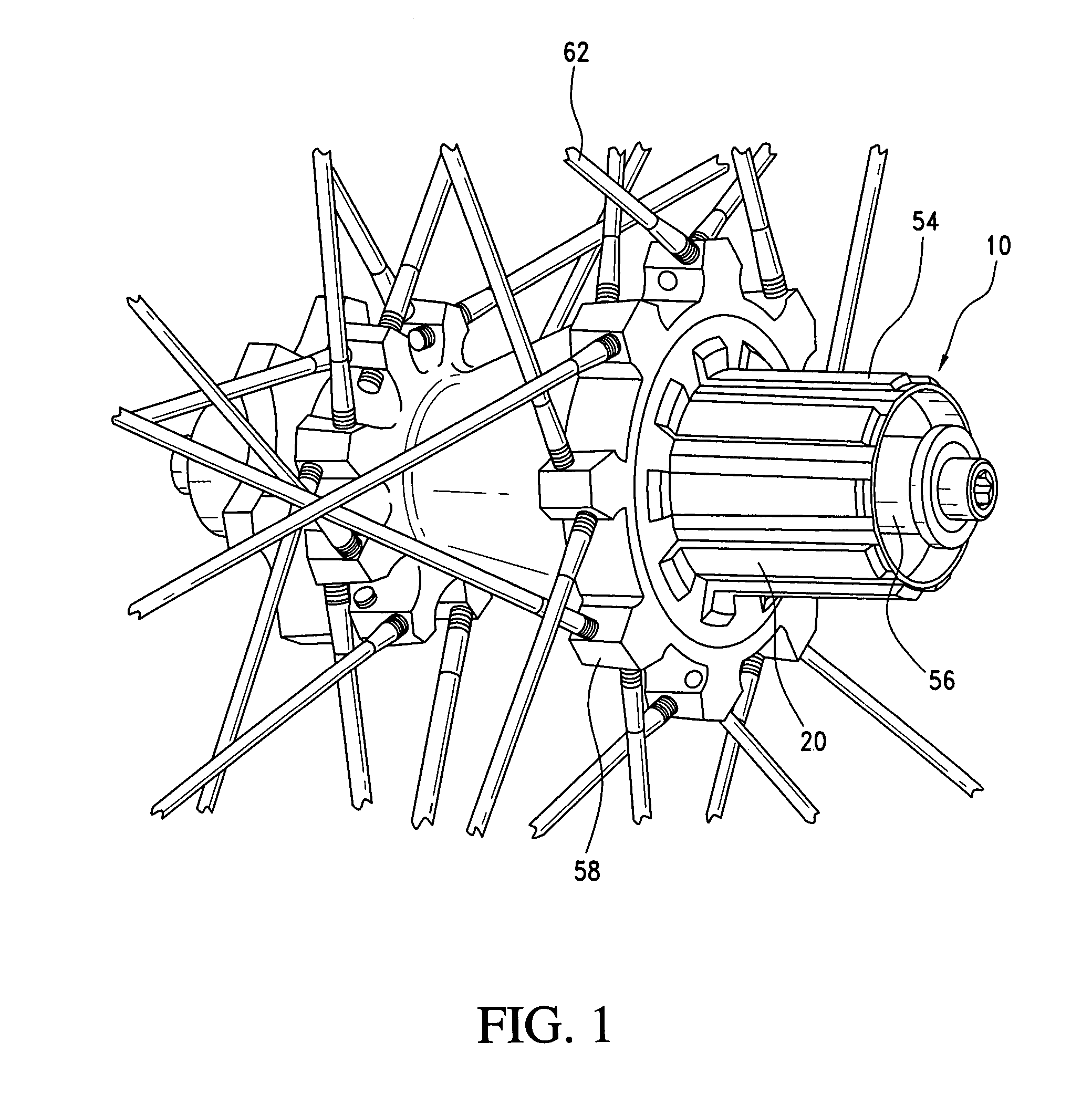
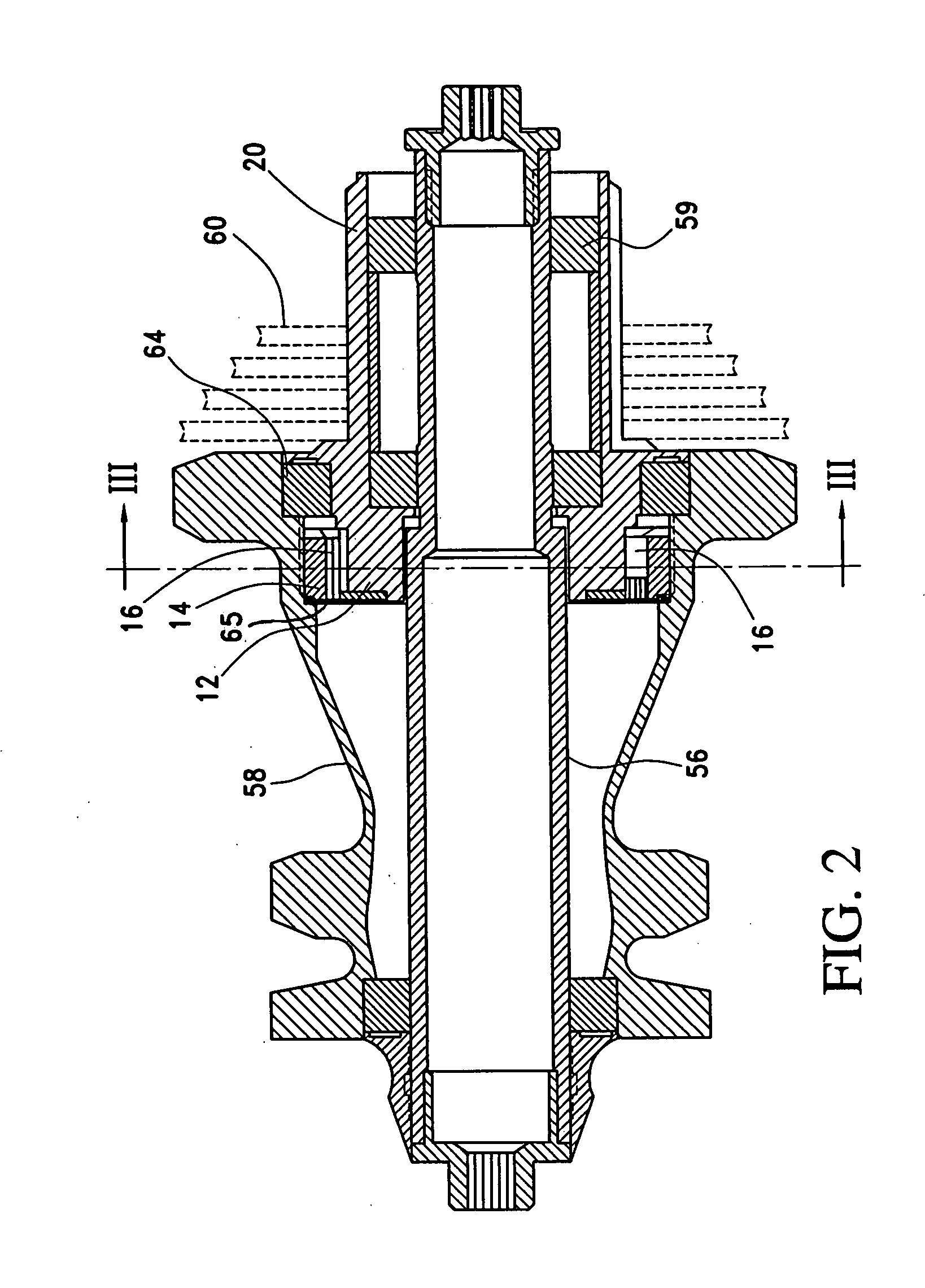
[0039] Referring to the various figures, a multi-tooth pawl type gearing mechanism 10 for a freewheel of a bicycle wheel hub 58 is disclosed. As with traditional freewheel construction, the present gearing mechanism 10 includes an inner rotor member 12 having an axis. The inner rotor member 12 forms part of a cassette body 20 upon which the sprockets 60 and drive chain (not shown) are mounted for the transfer of power thereto during pedaling in a manner well known to those skilled in the art. The inner rotor member 12 is surrounded by a gear ring 14 having an external circumference surface and ...


PUM


Abstract

A multi-tooth pawl type gearing mechanism for a freewheel of a bicycle wheel hub includes a cassette body having an inner rotor member with an axis. A gear ring shaped and dimensioned for attachment to a wheel hub of a bicycle wheel is also provided allowing for the transferring of power from the gear ring to the bicycle wheel. The gear ring surrounds the inner rotor member and includes an inner surface. A series of pawls, wherein each pawl includes a first end and a second end, are positioned between the inner rotor member and the gear ring for transmitting power therebetween in a unilateral direction as the inner rotor member is rotated. When the inner rotor member is rotated in a first direction the pawls are brought into engagement with the inner surface of the gear ring thereby transmitting rotation of the inner rotor member to the gear ring and when the inner rotor member is rotated in an opposite second direction the pawls slide over the inner surface of the gear ring and rotation of the inner rotor member is not transmitted to the gear ring.

Description

CROSS REFERENCE TO RELATED APPLICATION [0001] This application claims the benefit of U.S. Provisional Application Ser. No. 60 / 801,383, entitled “MULTI-TOOTH PAWL TYPE GEARING MECHANISM”, filed May 19, 2006.BACKGROUND OF THE INVENTION [0002] 1. Field of the Invention [0003] The invention relates to a freewheel mechanism for a bicycle wheel hub. More particularly, the invention relates to a freewheel mechanism including a multi-tooth pawl assembly. [0004] 2. Description of the Prior Art [0005] Many mechanisms for transferring human power into motion on a wheeled type vehicle, for example, a bicycle, have been developed. As those skilled in the art will certainly appreciate, the transfer of human power to a bicycle has commonly been accomplished through leg motion. Most often, the leg motion is transferred to the bicycle through a mechanism employing some sort of chain connected to, and driving, a bicycle wheel. [0006] There has always been a need for a mechanism which engages in one d...

Claims


Application Information

Patent Timeline
IPC IPC(8): F16D13/04
CPCF16D41/30
Inventor SPIEGEL, CLINTON J.KIFFMEYER, JOHN
Owner TURNAMICS
Learn More