
Stackable insulated unit for wall construction and method of fabrication thereof

a technology of stackable units and walls, applied in the direction of structural elements, building components, construction materials, etc., can solve the problems of time-consuming and considerable effects of standard operation, and achieve the effect of convenient mounting, fast construction, and quick stacking on on

Active Publication Date: 2008-04-10
THERMO STRUCTURE
View PDF19 Cites 29 Cited by
  • Summary
  • Abstract
  • Description
  • Claims
  • Application Information

AI Technical Summary

Benefits of technology

[0016] An advantage of the present invention is that the unit for wall construction is insulated and can be easily mounted on a subjacent unit with the stud longitudinal sections providing the structural support approved for load-bearings under construction codes.
[0017] Another advantage of the present invention is that the unit for wall construction could be prefabricated at another location than the wall construction site.
[0018] A further advantage of the present invention is that the units for wall construction being relatively lightweight, can be quickly stacked on one another.
[0019] Yet another advantage of the present invention is that the unit for wall construction enables fast construction of rigid insulated walls.
[0020] Still another advantage of the present invention is that the unit for wall construction relies on the insulation material to provide structural rigidity to the unit and support to the unit components, thereby securing the two sides wooden planks to the stud longitudinal sections, without the use of any other fastening members.
[0021] Another advantage of the present invention is that the unit for wall construction includes stud longitudinal sections extending into through openings and secured to the unit, the stud longitudinal sections being used to support the structural transversal, typically vertical, loads transmitted through the wall structure.

Problems solved by technology

This standard operation can be time consuming and have considerable effects in areas where the residential building period is constrained to a few months of the year due to for example a harsh winter climate.

Method used


Image

  • Stackable insulated unit for wall construction and method of fabrication thereof
  • Stackable insulated unit for wall construction and method of fabrication thereof
  • Stackable insulated unit for wall construction and method of fabrication thereof

Examples


Embodiment Construction

[0051] With reference to the annexed drawings the preferred embodiments of the present invention will be herein described for indicative purpose and by no means as of limitation.

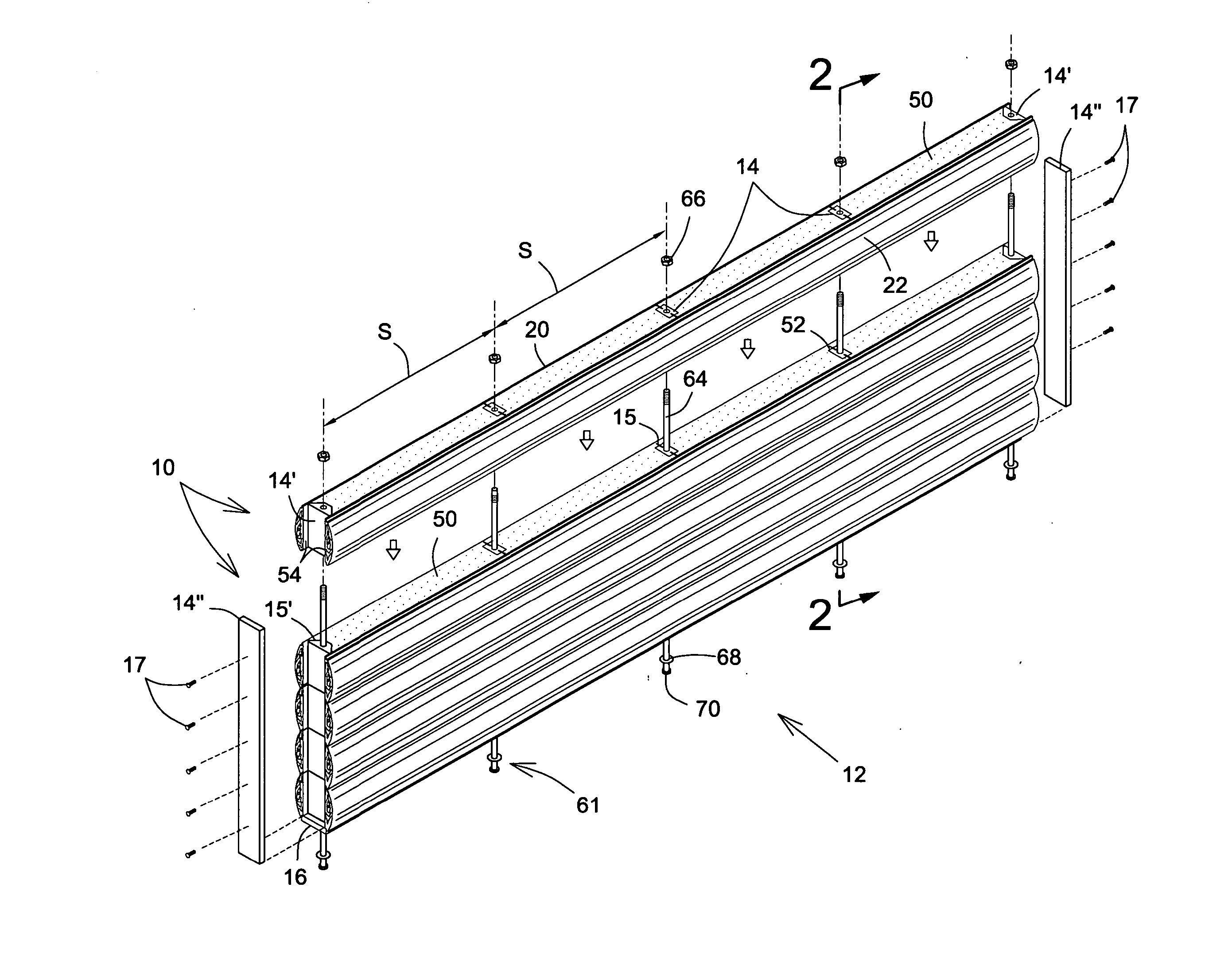
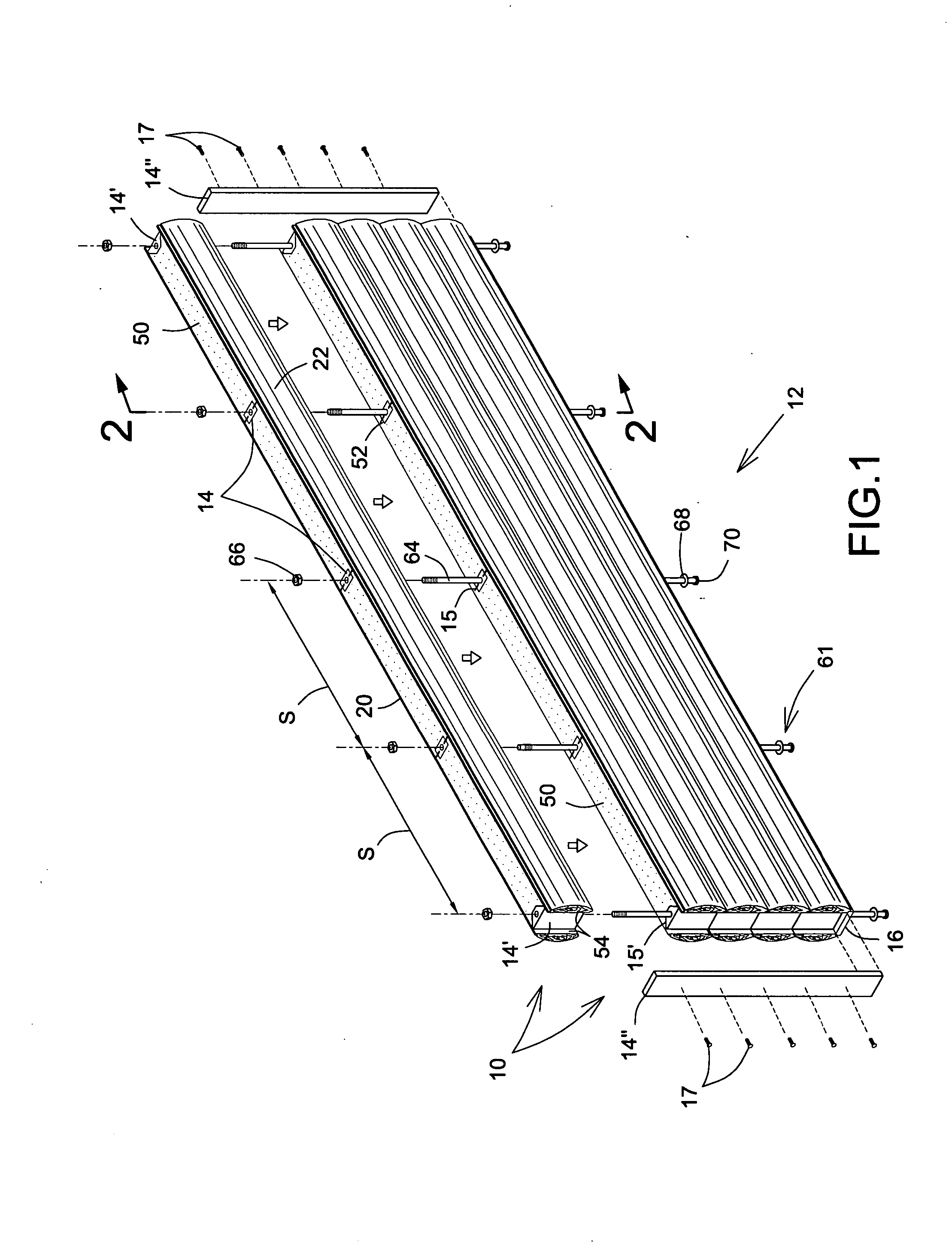
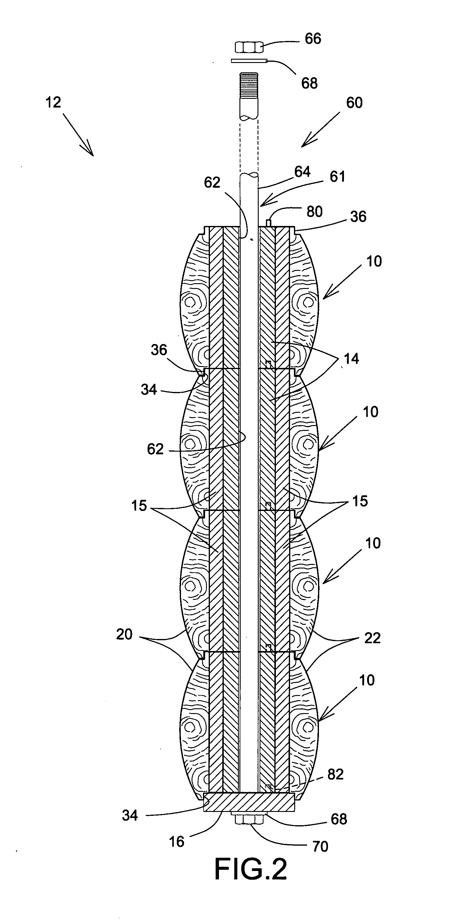
[0052] Referring to FIG. 1, there is shown an embodiment of a stackable unit 10 in accordance with the present invention to be used in a wall construction 12. The preferably rectangular and generally longitudinal unit 10 comprises mainly a pair of wooden planks, generally flat timber, assembled side planks 20, 22 or the like, which could be engineered wooden planks (EWP), sandwiching a heat insulating core 50 made of expandable urethane, polyurethane, foamable plastic polymer or the like material injected therein to fill in all the voids or cavities located there between by expanding and curing during fabrication, as detailed hereinbelow. The height H of each wall construction unit 10 is typically of approximately seven to eight (7-8) inches, whilst the length is generally of a multiple of sixteen (16) or t...


PUM

PropertyMeasurementUnit
Thicknessaaaaaaaaaa
Forceaaaaaaaaaa
Pressureaaaaaaaaaa

Abstract

A stackable insulated unit for wall construction for forming a self-supporting wall structure consists of two side wooden planks spaced apart and secured to one another with an intermediate insulating layer bonded thereto, and a plurality of stud longitudinal sections transversely extending through the insulating layer and being secured thereby. The insulating layer ensures structural integrity of the stackable unit. The stud sections are preferably spaced from at least one of the side planks. The invention also includes the method of fabrication of stackable unit.

Description

CROSS REFERENCE TO RELATED APPLICATIONS [0001] The present application is a continuation-in-part (C.I.P.) of application Ser. No. 11 / 485,256, filed on Jul. 13, 2006, which claimed benefit of U.S. Provisional Applications for Patent Ser. No. 60 / 700,723, filed on Jul. 20, 2005, and Ser. No. 60 / 733,171, filed on Nov. 4, 2005.FIELD OF THE INVENTION [0002] The present invention relates to a wall building construction unit and methods and is more particularly concerned with a prefabricated insulated and stackable element, and method of fabrication thereof. BACKGROUND OF THE INVENTION [0003] It is well known in the art to build wooden frameworks for housing walls. An insulating core is then usually inserted in-between the studs and lintels or headers and closed with facing panels. This standard operation can be time consuming and have considerable effects in areas where the residential building period is constrained to a few months of the year due to for example a harsh winter climate. [00...

Claims


Application Information

Patent Timeline
IPC IPC(8): E04B2/28E04B1/35E04B1/62E04B2/70E04C1/41E04B2/30E04B2/02
CPCB29C44/1233E04B2001/3583E04B2/702
Inventor TIBERI, SYLVAINMATHON, MICHEL
Owner THERMO STRUCTURE
Learn More