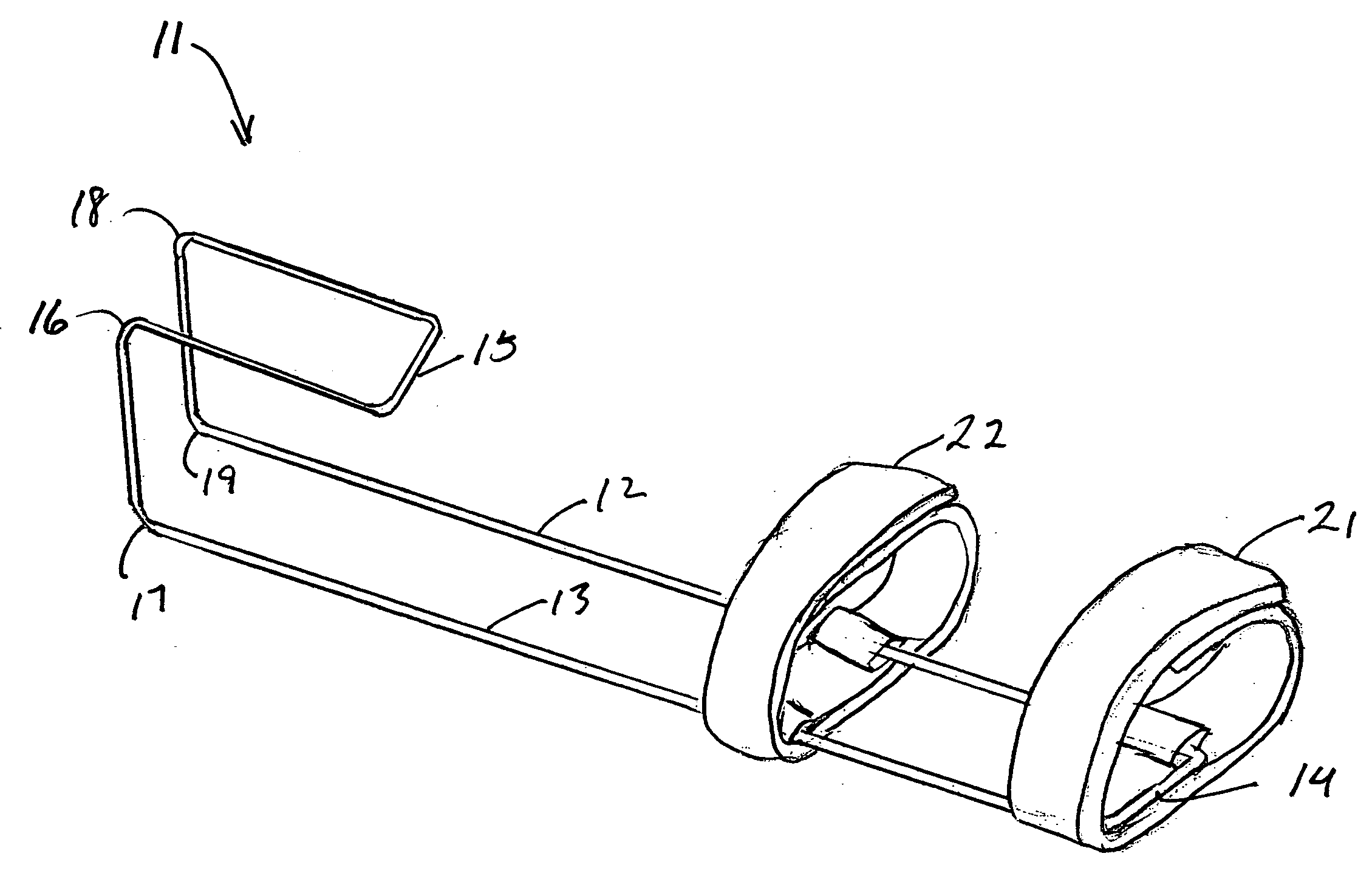
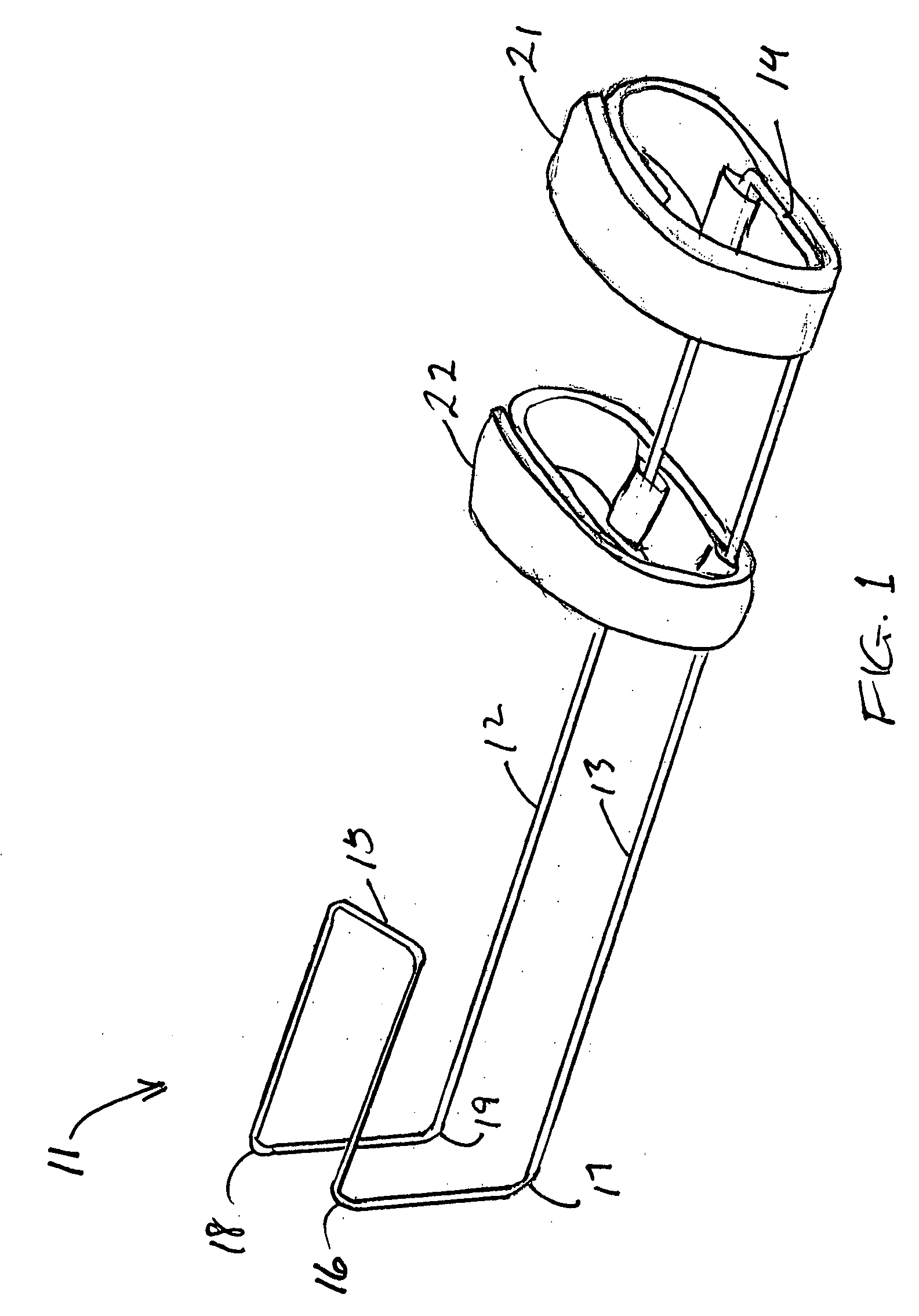
[0013]This invention resides in a wrist splint that includes a dorsal bar and a pair of rods extending from one end of the bar, the rods spaced apart by a sufficient width to permit the passage of the wearer's
middle finger between them and curved in the palmar direction to pass through the wearer's web spaces on either side of the middle finger. The rods extend a
short distance over the palm, securing the rods to the hand at the base of the middle finger and thereby maintaining alignment of the palm with the
forearm. In certain embodiments the dorsal bar is itself a pair of rods which are an extension of the two rods that pass through the web spaces, while in other embodiments the dorsal bar is a unitary bar to which the proximal ends of the rods are embedded or otherwise secured. In either case, the bar and rods are rigid or semi-rigid and the splint is shaped to extend from the back of the
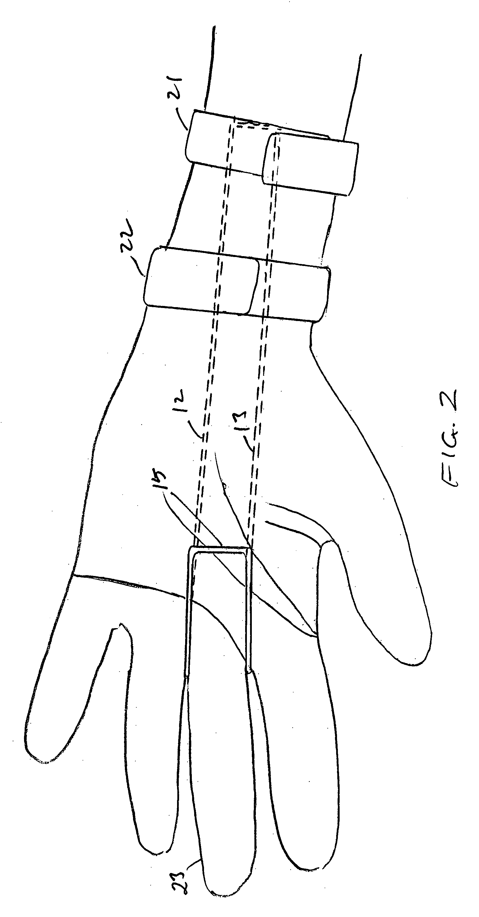
forearm and from there to pass distally over the back of the wrist and hand, then to pass between the middle finger and adjacent fingers at the base of the middle finger toward the palm, preferably with one rod on each side of the middle finger. In preferred structures, the palmar ends of the rods terminate at approximately the mid-palm. The ends of both rods at the mid-palm (i.e., the distal ends) can be joined such that the two wires form a loop. The proximal (forearm) ends of the rods are securable to the forearm by one or more double-sided VELCRO straps or their equivalents, such as elastic bands or any rigid or flexible cuffs that are secured by straps, clasps, snaps, buttons, or any other conventional fasteners. In preferred embodiments of the invention, two such cuffs or VELCRO straps are used, the one closest to the
elbow encircling the forearm approximately midway between the wrist and
elbow, and the other encircling the forearm at a location immediately proximal to the wrist, at the site where one would wear a wristwatch.
[0014]Among the advantages of wrist splints of this invention are that the area between the
thumb and
index finger remains entirely uncovered and unconstrained when the user is wearing the splint. This avoids chafing and any limitation on the motion of the
thumb and
index finger. Also, the splint material is far removed from the thumb, thereby preserving critical functions of the hand. Further still, the area at the wrist where the superficial radial nerve is vulnerable to compression from the proximal edge of the thumb hole in a conventional wrist splint remains entirely uncovered.
Irritation of the superficial radial nerve by the splint is thus avoided. Preferred splints of this invention contain no components of other elements that limit the movement of any of the wearer's fingers to any substantial degree, and no rods, straps or other components that would pass over the wearer's webs other than the two webs on opposite sides of the middle finger.
[0015]
Wrist splints of this invention do not place any fabric in contact with the hand itself. With a splint in place, therefore, the
entire hand can be washed thoroughly with the same efficiency and effectiveness as if one were wearing a wristwatch. The wearer is also fully capable of forming a
fist while the wrist splint is in place. Also, no portion of the wrist splint contacts the hand at the region of the
carpal tunnel. There is thus no danger of tight application of the splint contributing to
carpal tunnel syndrome. At the distal hand, the splint in the preferred embodiments of this invention adds only the thickness of four rods to the cross-sectional bulk of the hand. In the region extending from mid-hand to mid-forearm, the only thickness added by the splint to the cross-section of the region, other than that of the two VELCRO straps, is the thickness of two rods and any covering pad that may be present (see the discussion of preferred embodiments below. The two VELCRO straps themselves add no more bulk than that of a wristwatch or a bracelet. With so little additional bulk, the wearer can wear a wristwatch, or button the
cuff of a long-sleeved shirt, easily over the splint, and because of the splint's extremely low profile, the splint does not interfere with the wearer's ability to slip the hand into a sleeve, a trouser pocket, or a deep purse. Under a long-sleeved shirt, only the two rods on the dorsum of the hand are visible, making the splint visibly unobtrusive. The wearer can also shake hands without the splint being noticed. Furthermore, the splint fits both left and right hands equally. The hand portions of the splint that are in ready
exposure to, and contact with, the environment are entirely impervious to
moisture, odors, and grime, and small objects can be held in the
fist without getting lost or caught. In terms of cost, the materials and labor required for manufacture of the splint are minimal.
