
Optical network system

a network system and optical network technology, applied in the field of optical network systems, can solve the problems of reducing wasting wavelength resources, and difficult to accommodate signals in the same frame in a mixed manner, so as to reduce the number of required devices, reduce the number of wavelength resources to be used, and increase the operation efficiency of wdm optical networks

Inactive Publication Date: 2008-04-03
FUJITSU LTD
View PDF3 Cites 46 Cited by
  • Summary
  • Abstract
  • Description
  • Claims
  • Application Information

AI Technical Summary

Benefits of technology

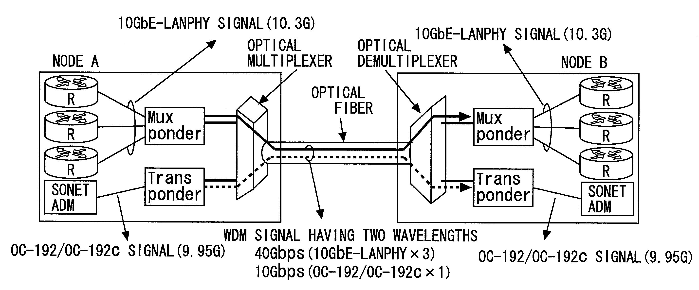
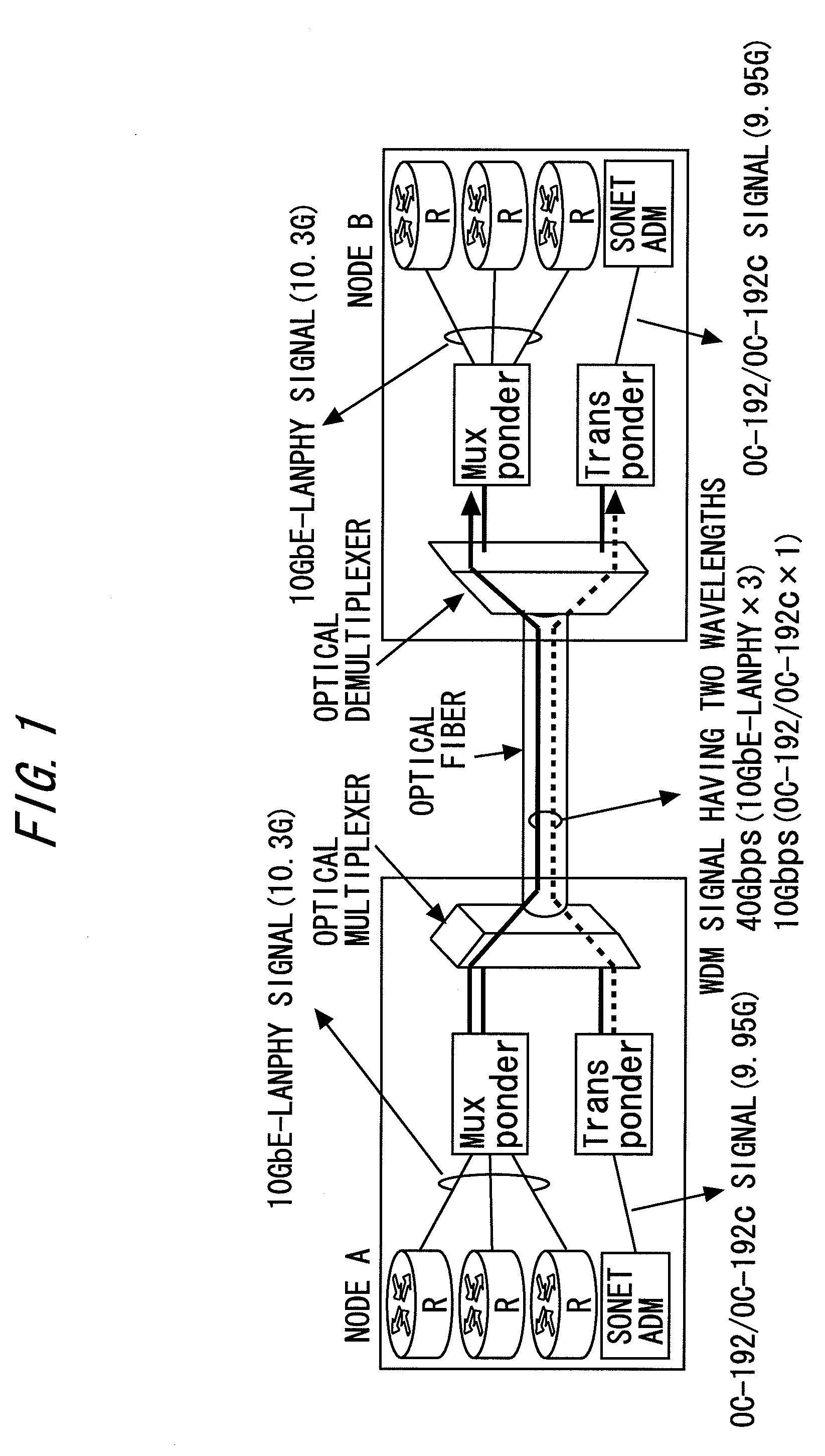
[0021]According to the present invention, it is possible to accommodate a SONET / SDH signal of about 10 Gbps or a 10 GbE-WANPHY signal and a 10 GbE-LANPHY signal in one wavelength in a mixed manner, so wavelength resources to be used can be reduced and the operation efficiency of a WDM optical network is increased due to an effective use of wavelength. Further, the number of required devices can be reduced.

Problems solved by technology

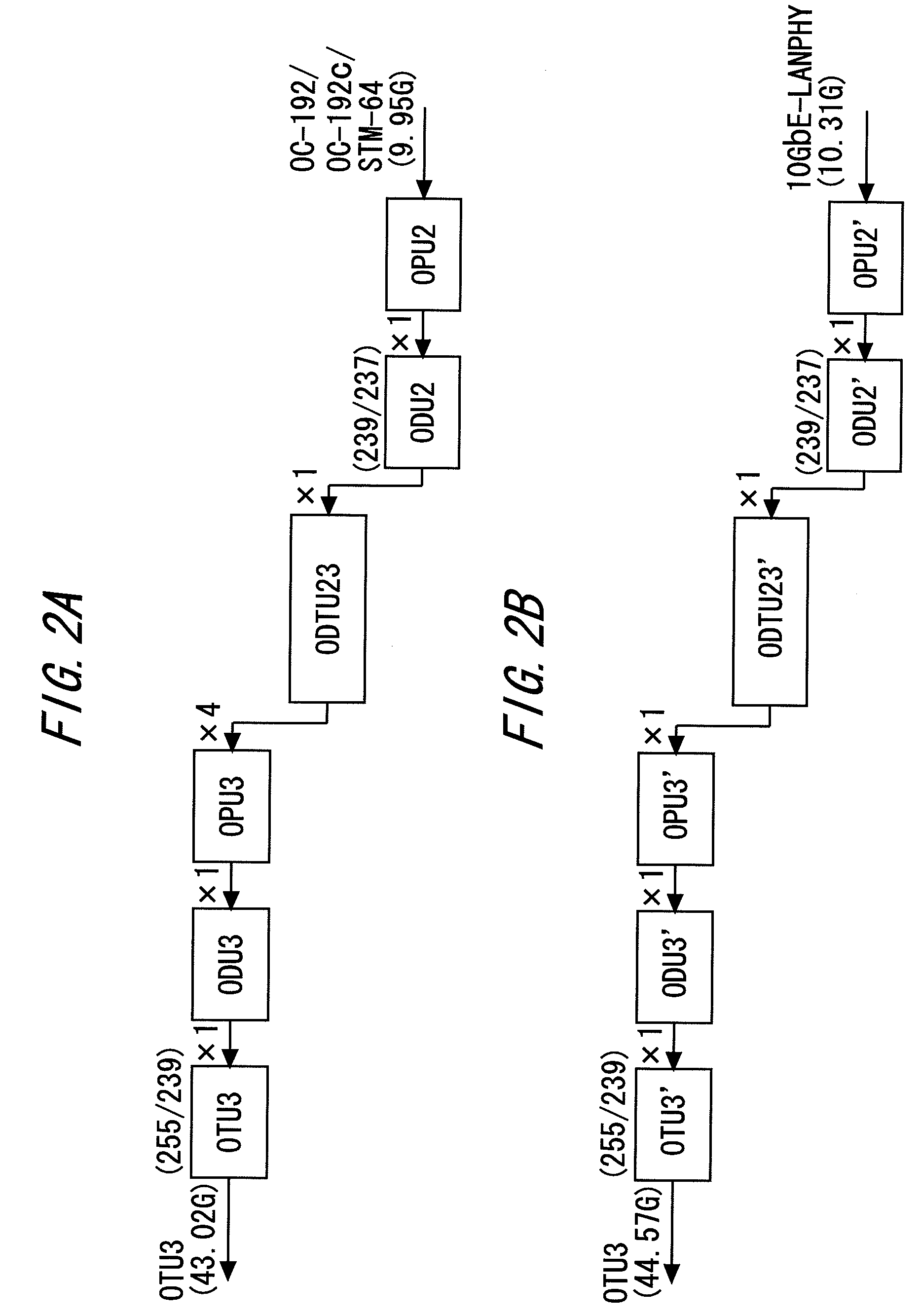
In the above description, when a SONET / SDH signal and a 10 GbE-LANPHY signal which serve as client signals having a transmission rate of about 10 Gbps are taken up, the respective client signals can be accommodated by applying 4-channel multiplexing thereto, but since both the signals have different transmission rates, i.e., 9.95 Gbps and 10.3 Gbps, it is difficult to accommodate the signals in the same frame in a mixed manner.
As a result, it is inevitable that wavelength resources are wasted and the operation efficiency of a WDM optical network is decreased.

Method used


Image

  • Optical network system
  • Optical network system
  • Optical network system

Examples


Embodiment Construction

[0035]Hereinafter, the present invention is described in more detail with reference to the accompanying drawings. The drawings show a preferred embodiment of the present invention. However, the present invention can be implemented in many different modes and it should not be construed that the present invention is limited to the embodiment described in this specification. The embodiment is rather provided so as to disclose this specification completely and perfectly and to inform those skilled in the art of the scope of the present invention sufficiently.

[Optical Network System Configuration]

[0036]Referring to FIG. 3 showing a system configuration according to an embodiment of the present invention, an optical network system (in this embodiment, referred to as photonic network system) SYS includes multiple Optical Add / Drop Multiplexing (OADM) devices 10, an optical fiber transmission line 30 connecting the OADM devices 10 in a ring-shaped manner, and a layer 2 switch device 21 and a...


PUM


Abstract

An optical transponder includes a mapping unit mapping, out of multiple types of signals including a first client signal and a second client signal that transmission rates are different from each other, the first client signal having a lower transmission rate to a Generic Framing Procedure (GFP) frame defined in ITU-T Recommendations; a coding unit applying 64B / 66B coding to the first client signal mapped to the GFP frame; and a multiplexing unit multiplexing the first client signal to which the 64B / 66B coding has been applied and the second client signal in a frame conforming to an Optical Transport Network (OTN) defined in ITU-T Recommendations; in which the first client signal and the second client signal are accommodated in an identical frame in a mixed manner and transmitted as an optical signal having one wavelength.

Description

BACKGROUND OF THE INVENTION[0001]The present invention relates to an optical network system in which multiple types of low-speed signals are accommodated in an identical frame of a high-speed signal in a mixed manner and transmitted (including exchanged and forwarded), and more particularly, to an optical signal transmission technique which allows both of a SONET / SDH signal of about 10 Gbps and a 10 GbE-LANPHY signal whose bit rates are different from each other to be accommodated in a single 40-Gbps wavelength path in a mixed manner and transparently mapped.[0002]In order to deal with an increased demand for data communications as represented by the Internet, larger-capacity communication systems are expected. As one of measures for larger capacity systems, increased-bit-rate communication systems have been studied. At this time, it is required to accommodate a conventional low-bit-rate signal in a frame of a high-speed signal whose bit rate is increased and transmit it.[0003]For e...

Claims


Application Information

Patent Timeline
Patent Type & Authority Applications(United States)
IPC IPC(8): H04J14/00
CPCH04J3/1664H04J3/22H04J14/0201H04J14/0226H04J14/0227H04J14/0245H04J14/0283H04J14/0284H04J2203/0067H04J14/0249H04J14/0279
Inventor KATAGIRI, TORU
Owner FUJITSU LTD
Learn More