
Method for determining a tooth period length of a bone milling cutter

a bone milling cutter and tooth period technology, which is applied in the field of manufacturing methods of bone milling cutters, can solve the problems of high cost, inability to manufacture generic bone milling cutters, and inability to manufacture generic types, and achieves good material removal, good tooth stability, and good dimensioning for precise working.

Active Publication Date: 2008-03-27
JOIMAX GMBH
View PDF4 Cites 96 Cited by
  • Summary
  • Abstract
  • Description
  • Claims
  • Application Information

AI Technical Summary

Benefits of technology

[0016]By selecting an even-number value for the number of the tooth period patterns distributed over the tube circumference, there can be achieved, in particular in the case of a simple tooth period pattern, in a particularly simple manner, a paired point-symmetrical arrangement of the tooth period patterns which strongly simplifies manufacture and thereby makes it less expensive. Opposing tooth period patterns can be processed simultaneously, while guaranteeing a radial course of cutting edges.
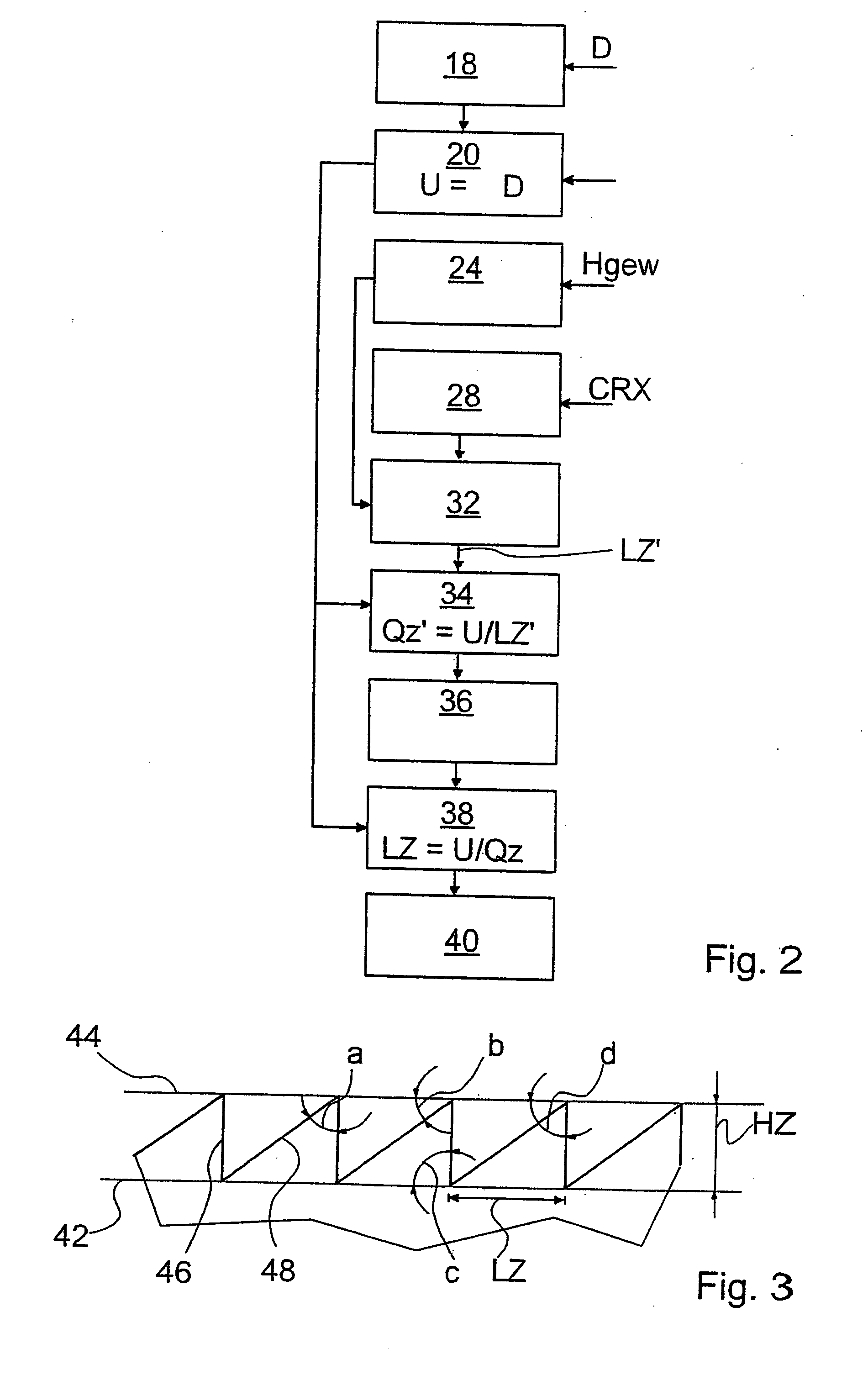
[0020]According to a particularly advantageous embodiment of the method according to the invention, an adaptation, in particular a scaling of the tooth height or an adaptation of the wedge angle and / or angle of incidence of the tooth period pattern can, after ascertaining the tooth period length, be carried out in order to set the ascertained tooth period length in an advantageous proportion to the tooth height. Thus, in certain circumstances, small deviations of the ultimate tooth height from the desired tooth height, as well as deviations of the ultimate ascertained tooth shape from the desired tooth shape, as determined by the given parameters of the tooth period pattern, can be tolerated.
[0023]If the height of the larger tooth and the height of the smaller tooth are determined starting from a common tooth tip line, substantial stability of the larger teeth can be achieved with highly effective material removal. Therefore, bone-milling cutters of this type with medium-sized double teeth are particularly suitable for precise work with good tooth stability and good removal of material.
[0025]A bone milling cutter which is particularly well dimensioned for precise working with good teeth stability and good material removal can be achieved by the method according to the invention if, when ascertaining the desired tooth period length from the tooth height of the milling cutter toothing, the length of the larger tooth of the tooth period pattern is determined such that it is ⅔ of the tooth height, with the length of the smaller tooth of the tooth period pattern being determined such that it is ⅓ of the tooth height, wherein the tooth period length corresponds to the sum of the lengths of the teeth.
[0027]Surprisingly, it was discovered that the effectiveness in the case of high stability is particularly high if, when ascertaining the desired tooth period length from the tooth height of the milling cutter toothing, the length of the larger tooth of the tooth period pattern is determined such that it is ⅗ of the tooth height and that the length of the smaller tooth of the tooth period pattern is determined such that it is ⅖ of the tooth height, wherein the tooth period length corresponds to the sum of the lengths of the teeth.

Problems solved by technology

For this reason, the manufacture of bone milling cutters of the generic type, which is additionally carried out in small numbers, is very expensive.

Method used


Image

  • Method for determining a tooth period length of a bone milling cutter
  • Method for determining a tooth period length of a bone milling cutter
  • Method for determining a tooth period length of a bone milling cutter

Examples


Embodiment Construction

[0038]FIG. 1 shows a bone milling cutter which has a hollow cylindrical milling cutter shaft 10, a handle, which is not depicted here, at its rear proximal end and a milling cutter toothing 12 of a first type at its front or distal end. The milling cutter shaft 10 has, at its proximal end, a recess 14 for fixing the handle.

[0039]Such a bone-milling cutter is employed in the field of medical technology to mill out vertebra components in the area of a lateral process of a spine vertebra in order to establish a postero-lateral access to pinched nerve roots of the central nervous system.

[0040]The bone milling cutter depicted in FIG. 1 is the direct product of a manufacturing method which, alongside known processing steps, in which, in the case of known sizes of bone milling cutters, this is made from a metal tube, comprises a method for determining the dimensions of the bone milling cutter, as is depicted in FIG. 2. In the latter method, there is determined in particular a tooth period ...


PUM

PropertyMeasurementUnit
Lengthaaaaaaaaaa
Angleaaaaaaaaaa
Diameteraaaaaaaaaa

Abstract

A method for manufacturing bone milling cutters, wherein a milling cutter toothing (12) is created at a distal face of a tubular milling cutter shaft (10) of a bone milling cutter at a given outer diameter (D) of the milling cutter shaft (10). The following steps are carried out: determining the tube circumference (U) of the milling cutter shaft (10); ascertaining an average desired tooth height (Hgew) of the milling cutter toothing (12); ascertaining the desired tooth period length (LZ′) of the milling cutter toothing from the desired tooth height (Hgew) at given parameters of a tooth period pattern; dividing the tube circumference (U) by the desired tooth period length (LZ); rounding the results to an even number value (Qz); and dividing the tube circumference (U) by the value (Qz) in order to obtain the tooth period length (LZ).

Description

[0001]This application claims Paris Convention priority of DE 10 2006 045 508.8 filed Sep. 27, 2006 the complete disclosure of which is hereby incorporated by reference.BACKGROUND OF THE INVENTION[0002]The invention relates to a method for manufacturing bone milling cutters, wherein a milling cutter toothing is created at a distal face of a tubular milling cutter shaft of a bone milling cutter at a given outer diameter of the milling cutter shaft as well as to a device for manufacturing bone milling cutters with which a milling cutter toothing is created at a digital face of a tubular milling cutter shaft of a tubular milling cutter shaft of a bone milling cutter at a given outer diameter of the milling cutter shaft. The invention further relates to a bone milling cutter with a tubular milling cutter shaft and a milling cutter toothing at a distal face of the tubular milling cutter shaft, wherein the milling cutter toothing is formed from a number of tooth period patterns periodical...

Claims


Application Information

Patent Timeline
IPC IPC(8): B23P15/34A61B17/16
CPCA61B17/1637A61B17/1671A61B17/32002A61B17/32053Y10T409/30A61B2017/00261A61B2017/00526A61B2019/481A61B17/3472A61B2090/08021A61B17/16
Inventor RIES, WOLFGANGNOTHEIS, MATHIAS
Owner JOIMAX GMBH
Learn More