
Closure and container neck

a container and closure technology, applied in the field of container closures, can solve the problems of insufficient visibility of tamper evidence, loss of sealing between the container closure and the container opening, and air in the sealed container

Inactive Publication Date: 2008-03-27
RBC TRUSTEES CI
View PDF6 Cites 20 Cited by
  • Summary
  • Abstract
  • Description
  • Claims
  • Application Information

AI Technical Summary

Benefits of technology

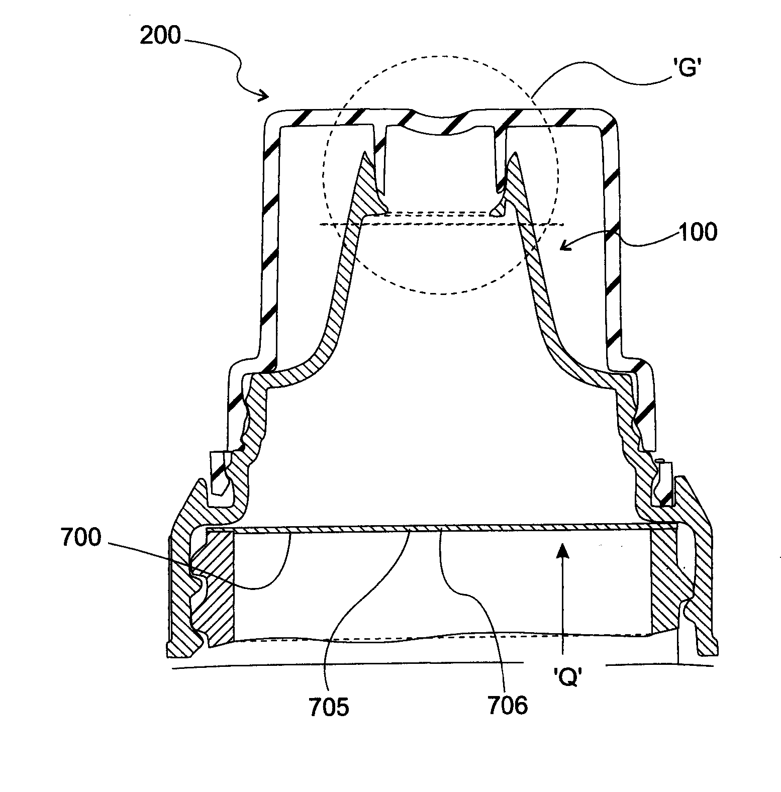
[0015] A further aspect of the present invention deals especially with the need for a proper relationship between sealing means and tamper-evidence means such that the tamper-evidence means operates prior to the seal being breached. This avoids the possibility apparent with many so-called tamper-evident closures whereby by malicious tampering or inappropriate application torque and / or relaxation of the closure causing the seal between closure and container neck to be breached without the tamper-evidence means operating and allowing the contents to be degraded by action of atmosphere or the malicious introduction of contaminants.

Problems solved by technology

One problem that exists with prior art tamper-evident closures is the loss of sealing between the closure and container opening prior to the tamper-evidence features operating and insufficient visibility of tamper evidence means.
A further problem is that air is often present within sealed containers and at least the oxygen and or moisture contained therein and or contained in air or oxygen which may after sealing permeate into the container may react with and degrade the contents.
The said prior art does not disclose oxygen or moisture reduction in sealed container using means associated with the closures disclosed herein.
However such flow control valves are relatively complicated and expensive to manufacture.
Additionally, prior art valves, especially those made of silicon rubber, typically require a retention means to hold and retain the valve in position.
This adds to the complexity and cost of manufacture and often necessitates the use of specialised machinery in order to manufacture the valve.

Method used


Image

  • Closure and container neck
  • Closure and container neck
  • Closure and container neck

Examples


embodiment 1

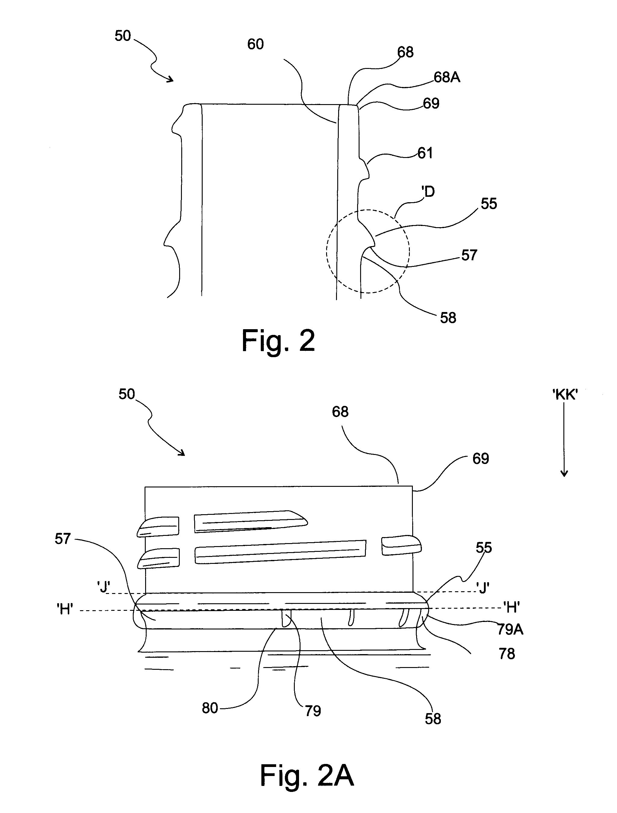
[0072] Embodiment 1 has joining edge 79A1 as a sloped curved shape with a convex curve viewed from ‘AA’ and

embodiment 2

[0073] Embodiment 2 has joining edge 79A2 as a linear sloped surface and

embodiment 3

[0074] Embodiment 3 has joining edge 79A3 as a sloped curved shape with a concave curve viewed from ‘AA’ and

[0075] In yet another embodiment 4 curved wall 58 between each engagement means 80 continues as indicated by dotted line 58A intersecting the upper surface of tamper bead 55 at edge 56 and creating an extension to engagement face 78 represented by hatched area 78A. Said curved wall 58 may have a compound curve having a varying radius at various points.

[0076] In yet another embodiment said wall 58 may be a linear surface not curved.

[0077] In yet another embodiment 5 the upper outer edge of engagement faces 78 may abut the lower surface 57 of said tamper bead 55 at a point radially inwards towards the axis of the said container neck for example at joining point 82 and leaving at least adjacent to engagement means 80 a portion of tamper bead lower surface 57 adjoining tamper bead upper surface 55A to engage at least with closures relying on contact between closure tamper eviden...


PUM


Abstract

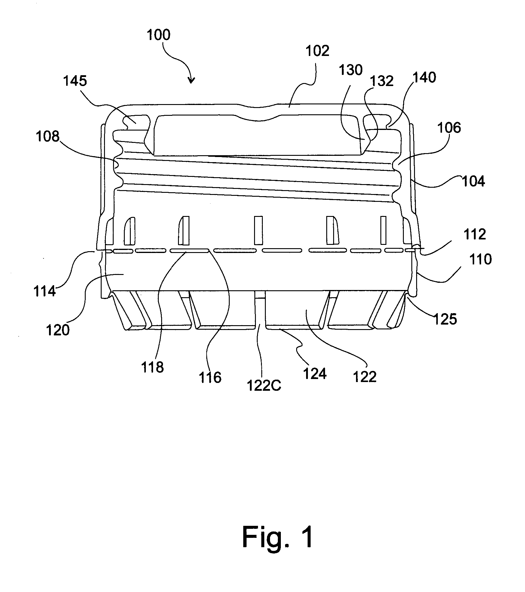
This invention relates to closures for containers, and more particularly to tamper-evident closures for containers. One aspect of the invention provides a container and a closure for connection to said container, said closure including: an upper wall (102); a skirt (104) formed integrally with and extending downwardly from said upper wall, said skirt adapted to engage with a neck portion of the container to secure the closure to the container; a tamper-evident band (110) frangibly connected to said skirt; the neck of a container including a tamper bead adapted to engage with tabs (122) on said tamper-evident band to facilitate separation of the band (110) from the skirt of the closure and an inwardly and downwardly sloping container neck surface beneath said tamper bead, said inwardly and downwardly sloping surface urging said separated tamper-evident band downwards away from said skirt.

Description

CROSS-REFERENCE TO RELATED APPLICATIONS [0001] This application is a continuation of PCT Application No. PCT / AU2005 / 001968, filed Dec. 23, 2005 which claims priority to Australian Application No. 2004907264, filed Dec. 23, 2004.FIELD OF THE INVENTION [0002] The present invention relates to closures for containers, and more particularly to tamper-evident closures for containers and including tamper evident dispensing closures and tamper evident child resistant closures together with corresponding container necks. BACKGROUND TO THE INVENTION [0003] Any discussion of the prior art throughout the specification should in no way be considered as an admission that such prior art is widely known or forms part of common general knowledge in the field. [0004] There exists extensive prior art in relation to the design and manufacture of tamper-evident closures for containers, such as for example U.S. Pat. No. 4,653,657 (Papavasilopolous), U.S. Pat. No. 4,807,771 (Roy), U.S. Pat. No. 5,660,288 ...

Claims


Application Information

Patent Timeline
IPC IPC(8): B65D35/38
CPCB65D1/023B65D41/0421B65D81/266B65D47/123B65D47/2031B65D41/3428B65D41/34B65D55/08B65D47/00B65D47/20B65D47/2018B65D47/2025B65D55/02
Inventor HIGGINS, CHRISTOPHER LYNDON
Owner RBC TRUSTEES CI
Learn More