
Air-fuel ratio control apparatus

a technology of air-fuel ratio and control apparatus, which is applied in the direction of electrical control, process and machine control, instruments, etc., can solve the problems of individual differences in the lift amount of the intake value, reducing the accuracy of adjustment of the intake air amount, and affecting the accuracy of control

Active Publication Date: 2007-06-07
TOYOTA JIDOSHA KK +1
View PDF21 Cites 22 Cited by
  • Summary
  • Abstract
  • Description
  • Claims
  • Application Information

AI Technical Summary

Benefits of technology

[0011] The invention provides an air-fuel ratio control apparatus that accurately controls the air-fuel ratio of an air-fuel mixture to a desired ratio in an internal combustion engine provided with a variable lift mechanism.
[0014] With this configuration, the deviation of the correction amount from the reference value is learned based on the lift amount of the intake valve, and used in the air-fuel ratio control. Accordingly, the fuel injection amount is increased or decreased by the correction amount so that the air-fuel ratio of the air-fuel mixture is adjusted to a desired air-fuel ratio, while the influence of the difference in the manner, in which the variable lift mechanism is operated, on the air-fuel ratio is suppressed by the correction using the learned deviation value. Accordingly, the air-fuel ratio of the air-fuel mixture is accurately controlled to the desired air-fuel ratio in the internal combustion engine including the variable lift mechanism.
[0023] With this configuration, the relationship is learned based on the deviation corresponding to the lift amount at which the influence of the deviation of the passage area of the communication portion from the reference area is most prominent. As a result, the relationship is learned accurately.
[0025] With this configuration, the relationship is learned when the internal combustion engine is at idle, that is, when the internal combustion engine is operating stably, in other words, when the deviation is stable. Accordingly, the relationship is learned accurately.
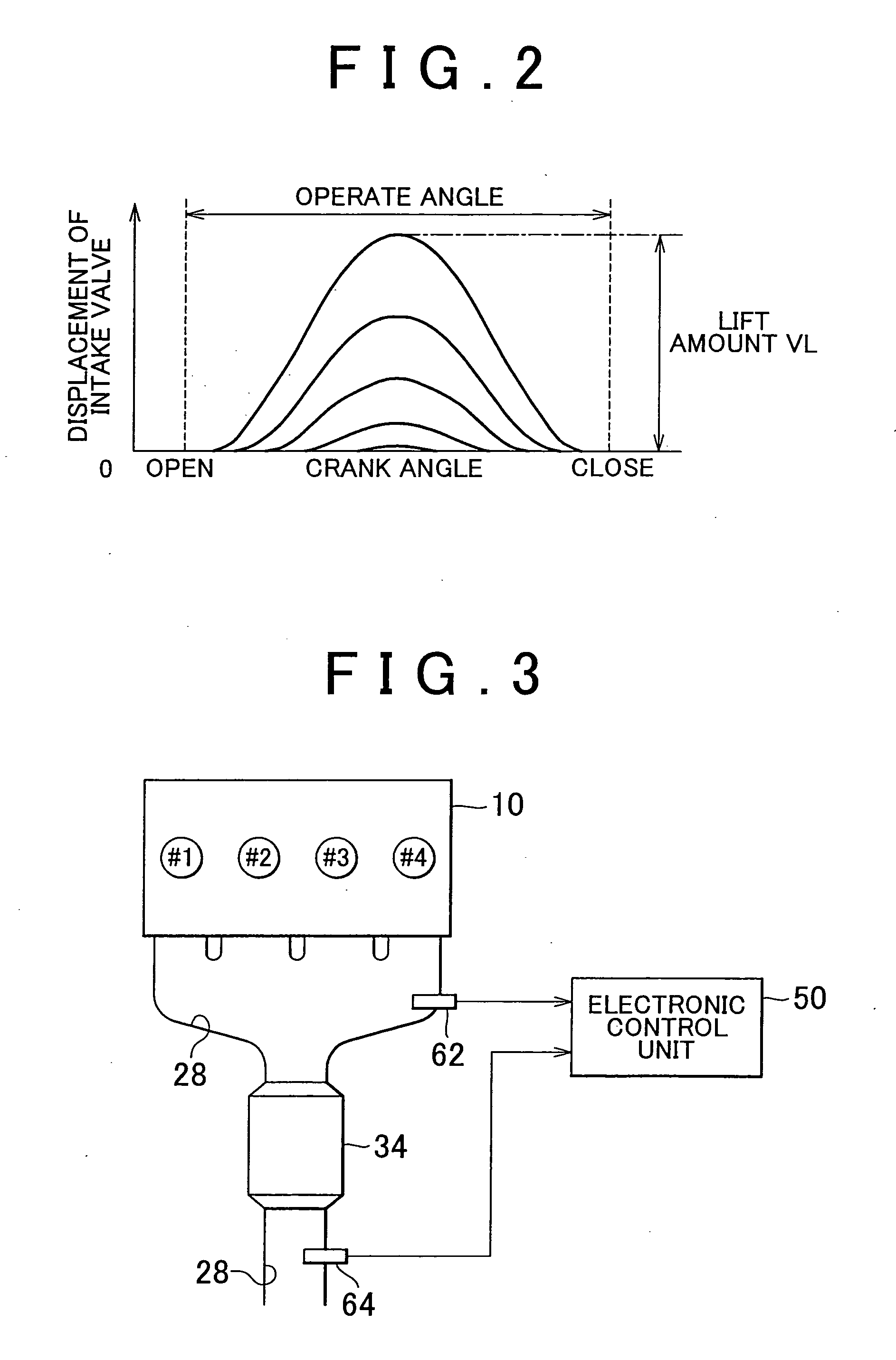
[0034] As described above, the fuel injection amount is corrected based on the signal output from the sensor provided upstream of the exhaust gas purification catalyst. In addition to this, there is provided the device that performs so-called sub-air-fuel ratio control, that is, corrects the fuel injection amount by the correction amount, which is increased or decreased by the predetermined amount, based on the signal output from the sensor provided downstream of the exhaust gas purification catalyst. Performing the sub-air-fuel ratio control makes it possible to adjust the fuel injection amount based on the actual exhaust gas purification action of the exhaust gas purification catalyst. As a result, the exhaust gas purification catalyst can purify the exhaust gas more efficiently. However, in the internal combustion engine including the variable lift mechanism, the deviation of the air-fuel ratio from the reference value is changed so frequently due to the frequent change in the lift amount of the intake value, it may not be possible to accurately increase or decrease the correction amount used in the sub-air-fuel ratio control.
[0035] With the configuration described above, the correction amount used in the sub-air-fuel ratio control can be accurately changed so that the change in the deviation of the air-fuel ratio from the reference value due to the change in the lift amount can be compensated for. As a result, the air-fuel ratio of the air-fuel mixture is accurately controlled to a desired ratio.

Problems solved by technology

There is an individual difference in the lift amount of the intake value, due to an influence of, for example, a fitting error.
Also, deposits may adhere to the intake valve with the operation of the internal combustion engine.
Such deviation of the actual passage area from the reference passage area contributes to reduced accuracy in adjustment of the intake air amount, and, consequently, reduced accuracy in adjusting the air-fuel ratio of the air-fuel mixture.
With such an apparatus, if the manner in which the variable lift mechanism is operated changes so frequently, it may not be possible to accurately compensate for the deviation of the air-fuel ratio from the reference air-fuel ratio, which is frequently changed in accordance with a frequent change in the manner described above.

Method used


Image

  • Air-fuel ratio control apparatus
  • Air-fuel ratio control apparatus
  • Air-fuel ratio control apparatus

Examples


first embodiment

[0053] Hereafter, the invention will be described in detail.

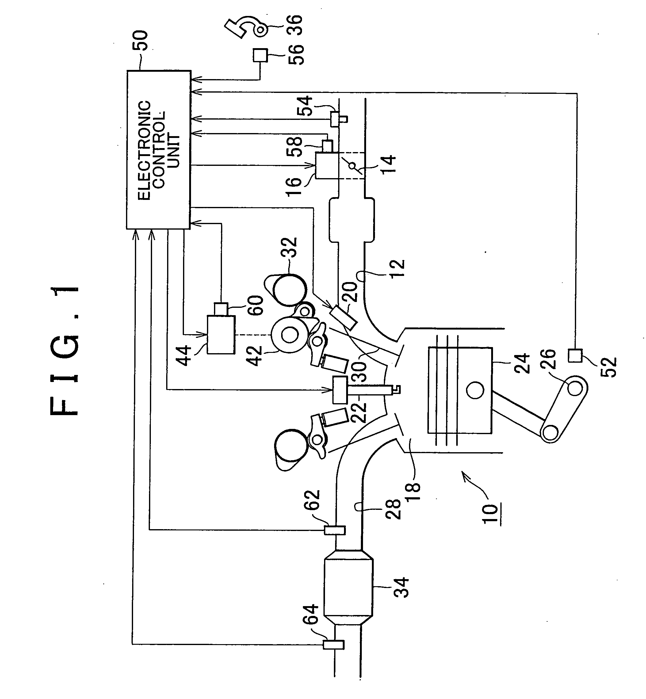
[0054]FIG. 1 schematically shows an air-fuel ratio control apparatus according to the first embodiment of the invention. As shown in FIG. 1, a throttle valve 14 is provided in an intake passage 12 of an internal combustion engine 10. A throttle motor 16 is connected to the throttle valve 14. The opening amount of the throttle valve 14 (the throttle valve opening amount TA) is adjusted by controlling the throttle motor 16, whereby the amount of air supplied into a combustion chamber 18 through the intake passage 12 is adjusted. A fuel injection valve 20 is provided in the intake passage 12. The fuel injection valve 20 injects fuel into the intake passage 12. In addition, an exhaust gas purification catalyst 34 is provided in an exhaust passage 28 of the internal combustion engine 10.

[0055] In the combustion chamber 18 of the internal combustion engine 10, the air-fuel mixture formed of the intake air and the injected fuel i...


PUM


Abstract

An air-fuel ratio control apparatus is applied to an internal combustion engine including a variable lift mechanism wich changes a lift amount of an intake valve. An oxygen sensor, wich outputs a signal indicating an oxygen concentration in exhaust gas, is provided downstream of an exhaust gas purification catalyst in an exhaust passage of the internal combustion engine. Air-fuel ratio control is performed to correct the fuel injection amount command value using the correction amount that is set based on the value output from the oxygen sensor. The relationship among the deviation of the correction amount from its reference value, the learned small lift value, the learned medium lift value, and the lift amount is learned. The learned deviation value is calculated based on the lift amount, using the learned relationship. Then, the fuel injection amount command value is corrected by the correction amount including the calculated learned deviation value.

Description

INCORPORATION BY REFERENCE [0001] The disclosure of Japanese Patent Application No. 2005-350560 filed on Dec. 5, 2005 including the specification, drawings and abstract is incorporated herein by reference in its entirety. BACKGROUND OF THE INVENTION [0002] 1. Field of the Invention [0003] The invention relates to an air-fuel ratio control apparatus for an internal combustion engine that includes a variable lift mechanism, which changes the lift amount of an intake value. The air-fuel ratio control apparatus also controls the air-fuel ratio based on a signal output from a sensor that detects the oxygen concentration in the exhaust gas present downstream of an exhaust gas purification catalyst. [0004] 2. Description of the Related Art [0005] In an internal combustion engine, the exhaust gas is usually purified by an exhaust gas purification catalyst provided in an exhaust passage. The exhaust gas purification catalyst efficiently purifies the exhaust gas, when the air-fuel ratio of th...

Claims


Application Information

Patent Timeline
IPC IPC(8): F02D41/00F01L1/34F01N3/00G06F17/00
CPCF01L1/185F01L13/0015F01L2001/0537F01L2105/00F01L2800/00F01N2560/025F01N2560/14F02D13/023F02D41/0002F02D41/1454F02D41/2454F02D41/2464F02D2041/001Y02T10/42Y02T10/18F01L2305/00Y02T10/12Y02T10/40
Inventor MORITA, HIROSHIIKEDA, KAZUTO
Owner TOYOTA JIDOSHA KK
Learn More