
External operation handle device

a handle and handle technology, applied in the direction of air-break switches, protective switch operating/release mechanisms, high-tension/heavy-dress switches, etc., can solve the problem of unstable holding the door panel by itself at the lock/unlock position, and achieve the effect of simple push operation and easy manipulation of the handle lock lever

Inactive Publication Date: 2008-03-27
FUJI ELECTRIC FA COMPONENTS & SYST CO LTD
View PDF12 Cites 8 Cited by
  • Summary
  • Abstract
  • Description
  • Claims
  • Application Information

AI Technical Summary

Benefits of technology

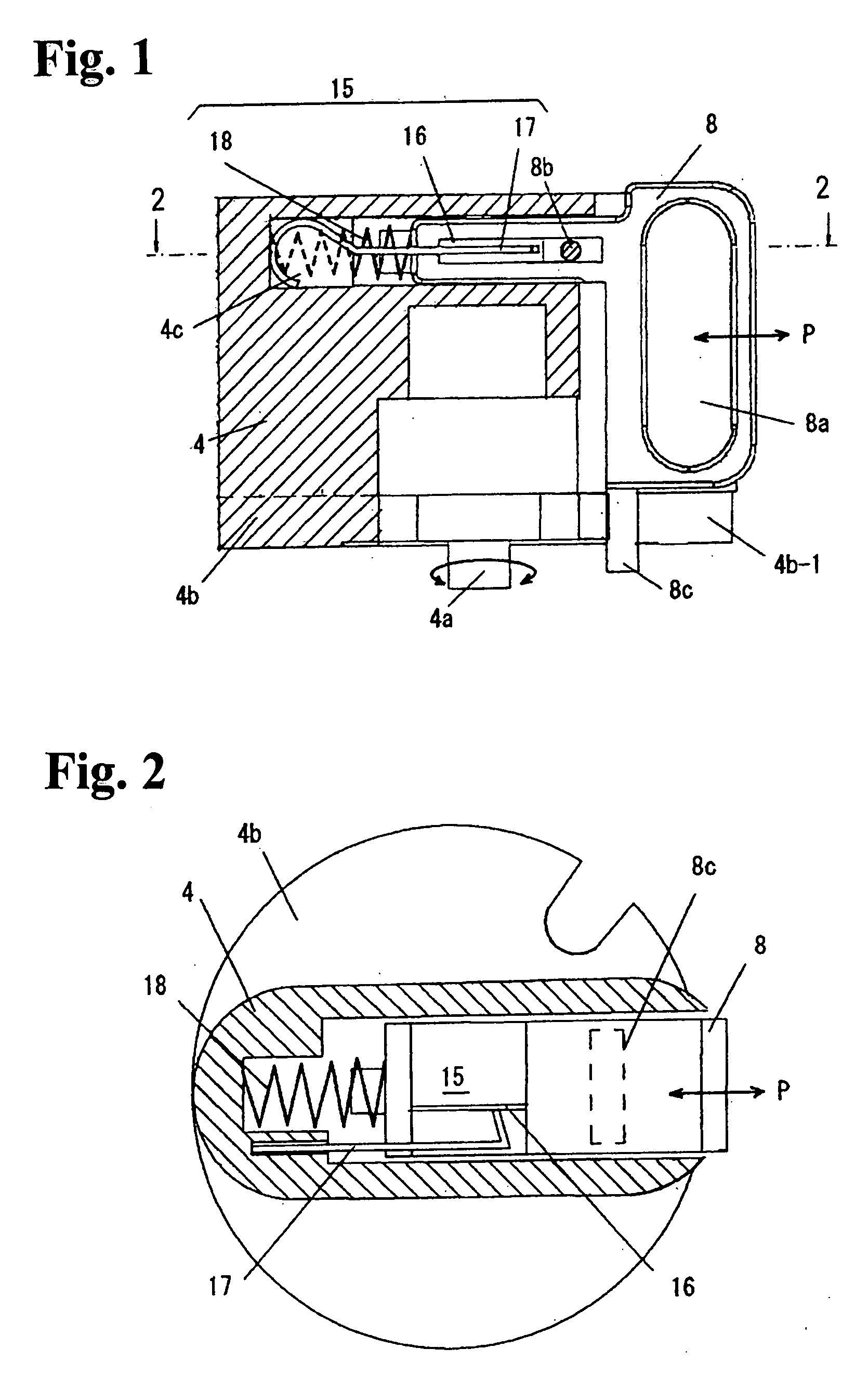
[0030]Consequently, when the interlock with the door panel of the switch board is unlocked to open the door panel, after turning the rotary handle to the OPEN position and moving the door lock lever to the unlock position, and by pushing the handle lock lever, the rotary handle is anchored and held at this OPEN position, and the door lock lever linked to the rotary handle is cramped and held at the unlock position. If the handle is released from a hand in this state, the door lock lever still stays at the unlock position as before without return motions. Therefore, the board panel can be opened safely.
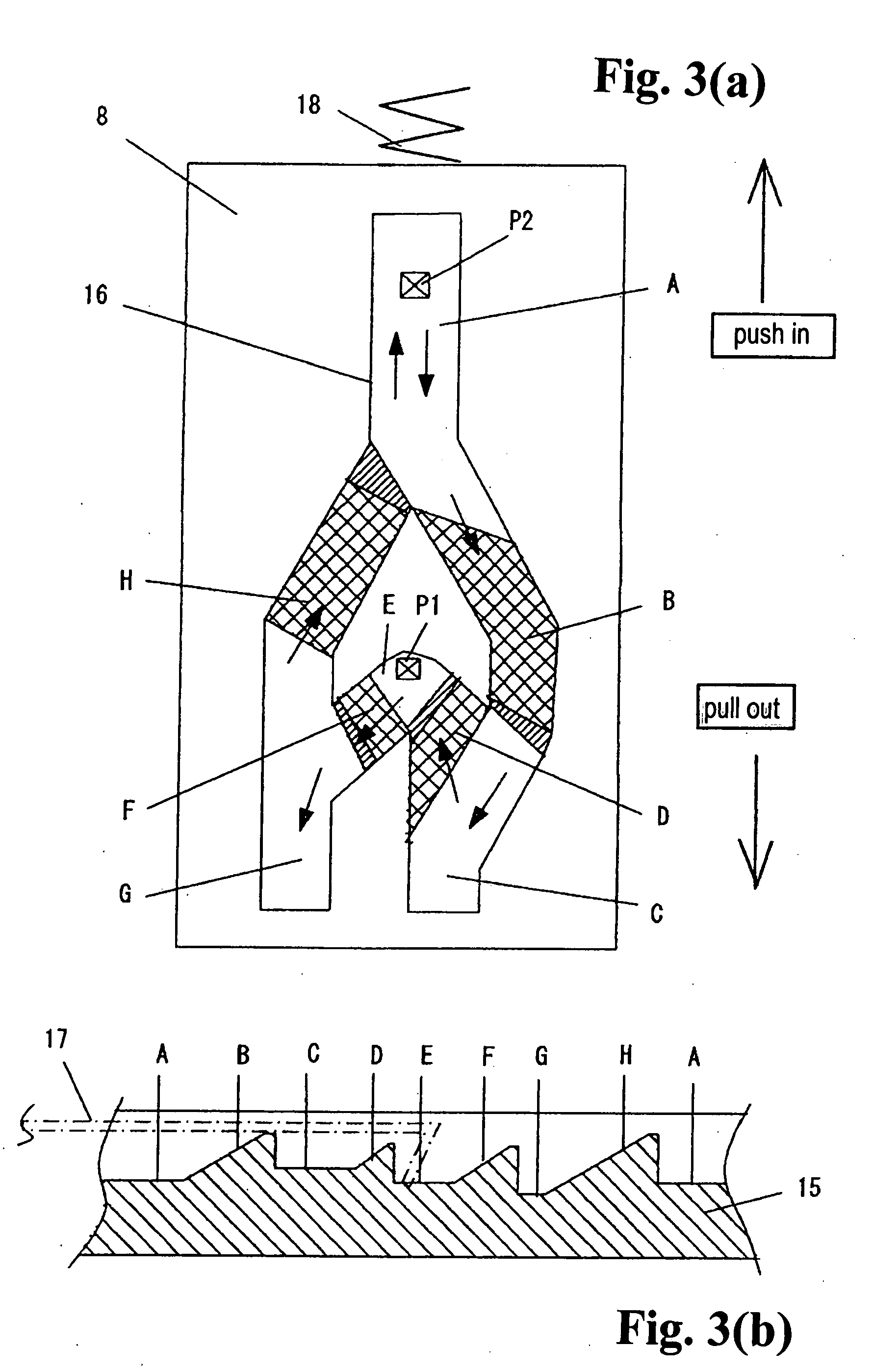
[0031]As the cam mechanism of an alternate operation type provided as a device for changing-over between pulling out and return positions of the handle lock lever, the change-over of the handle lever can be carried out by a simple push operation. Therefore, manipulation of the handle lock lever is made easier in the course of locking operations at ON, OFF, and OPEN positions.

Problems solved by technology

The external operation handle device having the conventional structure as described above, however, has the following problems about operation and performance of the door panel lock mechanism and handle lock mechanism thereof.
Consequently, it may become unstable to hold the door panel by itself at the lock / unlock position due to deformation of the leaf spring 13 during a long term operation.

Method used


Image

  • External operation handle device
  • External operation handle device
  • External operation handle device

Examples


Embodiment Construction

[0043]Some preferred embodiments according to the present invention will be described with reference to FIGS. 1 through 6, in which FIGS. 1 and 2 show a structure of the rotary handle; FIGS. 3(a) and 3(b) show a development of an alternate operation type cam mechanism provided in a handle lock lever; FIG. 4 is a plan view of a handle cover; FIG. 5 shows a structure of a door lock lever provided on the back surface of the handle cover; and FIG. 6 shows an overall structure of an external operation handle device combined with a circuit breaker. The same members in the embodiment are given the same symbols as in FIGS. 7 through 10 and description is omitted.

[0044]The external operation handle device shown in FIG. 6 has basically a similar structure to the conventional structure as shown in FIGS. 7 and 8. Nevertheless, the rotary handle 4 of the embodiment shown in FIG. 6 comprises a newly added cam mechanism 15 of an alternate operation type, details of which will be described hereinaf...


PUM


Abstract

An external operation handle device for a circuit breaker includes a rotary handle equipped with a handle lock lever, a drive mechanism linking the rotary handle and the locker handle of the circuit breaker, and a door lock lever for interlocking between the rotary handle and a door of the board. By operating the rotary handle, the circuit breaker can be turned to an ON or OFF position, and the door is unlocked at an OPEN position. The handle lock lever is slidably disposed on the rotary handle to be anchored and held at a pulled out position in a condition where the rotary handle at the OPEN position unlocks the door of the board, and the door lock lever linked to the rotary handle is cramped and held at the unlock position in a condition where the rotary handle is at the OPEN position.

Description

BACKGROUND OF THE INVENTION AND RELATED ART STATEMENT[0001]The present invention relates to an external operation handle device used in circuit breakers, for example, a molded case circuit breaker, an earth leakage breaker, and the like.[0002]An external operation handle device, an accessory device for a molded case circuit breaker, an earth leakage breaker, and the like, is known (for example, Patent Document 1: Japanese Unexamined Patent Application Publication No. 2005-149918), which operates a circuit breaker disposed inside a switch board, a control board, or the like, for open and close operations of the circuit breaker from outside of the board.[0003]The external operation handle device has a rotary handle and a drive mechanism mounted on a mounting base, the drive mechanism linking the rotary handle and a locker handle of the circuit breaker. The external operation handle device assembled with the circuit breaker disposed inside the board is operated by rotating the rotary h...

Claims


Application Information

Patent Timeline
Patent Type & Authority Applications(United States)
IPC IPC(8): H01H33/48
CPCH01H9/22H01H2071/565H01H71/56H01H9/281H01H71/52H01H71/10
Inventor EMURA, TAKESHIOSAWA, MAKOTOISHIDO, HIDEKI
Owner FUJI ELECTRIC FA COMPONENTS & SYST CO LTD
Learn More