
Auxiliary power supply apparatus and method

Inactive Publication Date: 2008-03-27
MOTION CONTROL ENG
View PDF12 Cites 22 Cited by
  • Summary
  • Abstract
  • Description
  • Claims
  • Application Information

AI Technical Summary

Benefits of technology

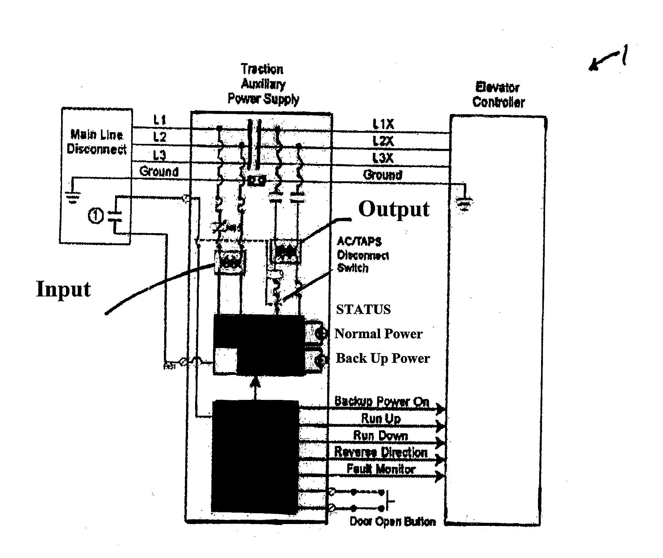
[0010] The present general inventive concept provides a power supply system and an auxiliary system control board. In the event of a power failure or disruption, the auxiliary system will send a signal to an elevator control board informing the elevator control board that the elevator is operating in emergency power status, which activat

Problems solved by technology

In the elevator industry, there is a potential that if a power supply fails, then an elevator car may become trapped in the elevator between floors.
If the primary power system fails, it is likely that any passengers and / or freight that are being transported within the elevator car will be stuck in between floors since the main power supply of convention elevator systems, in the event of a power failure, does not provide sufficient power to allow the elevator car to proceed to the next floor and open the elevator door for the passenger to exit the elevator car or for freight to be removed.
This can be a frightening and dangerous situation for a trapped passenger or can delay business activity if freight is trapped, which is aggravated if power is unable to be quickly restored.
However, these emergency systems do not prevent entrapment in the elevator car for at least a period of time.
Entrapment becomes exceptionally dangerous if there is a fire.
Conventional back-up power supplies are only capable of lowering the elevator and do not have enough power to move the elevator car to an upper floor.
Further, even if the conventional back-up power supplies had enough power to move the elevator car to an upper floor, conventional elevator control systems do not have any embedded logic required to assist the control system in determining which direction the load was moving without the use of standard load weighing devices.
Still further, conventional back-up power supply systems use a battery to operate when the primary source of power is lost and the power supply from the battery can be limited, especially if there is more than one elevator car.
If the back-up battery system fails, then passengers or freight will be trapped.
Another problem with conventional battery back-up systems is that the battery will lose power overtime and may not have enough power to move the elevator car to a floor and open the door to allow the passengers to get off of the elevator car safely.

Method used


Image

  • Auxiliary power supply apparatus and method
  • Auxiliary power supply apparatus and method

Examples


Embodiment Construction

[0014] A detailed embodiment of the present general inventive concept is disclosed herein; however, it is to be understood that the disclosed embodiment is merely exemplary of the principles of the invention, which may be embodied in various forms. Therefore, specific structural and functional details disclosed herein are not to be interpreted as limiting, but merely as a basis for the claims and as a representative basis for teaching one skilled in the art to variously employ the present general inventive concept in virtually any appropriately detailed structure.

[0015] Reference will now be made in detail to the embodiments of the present general inventive concept, examples of which are illustrated in the accompanying drawings. The embodiments are described below in order to explain the present general inventive concept by referring to the FIGURES.

[0016] The present general inventive concept is directed to an auxiliary power supply system or auxiliary system 1 including a power s...


PUM


Abstract

An auxiliary power supply apparatus and method thereof including a backup battery system having a power supply and a control board to provide an auxiliary power to an elevator control system upon failure of a primary power so that an elevator car may run to a next available upward or downward landing and open at least one door to the elevator.

Description

CROSS-REFERENCE TO RELATED APPLICATIONS [0001] This application claims the priority of U.S. Provisional Patent Application No. 60 / 824,968, filed on Sep. 8, 2006, in the United States Patent & Trademark Office, the disclosure of which is incorporated herein by reference in its entirety.BACKGROUND OF THE INVENTION [0002] 1. Field of the Invention [0003] The present general inventive concept relates generally to auxiliary power supply apparatus and methods of motion control systems such as backup battery systems comprising a power supply and a control board, and more particularly, to an auxiliary power supply system capable of supplying a secondary power to an elevator control system upon failure of a primary power so that an elevator may run to a next available landing and open a door to the elevator. [0004] 2. Description of Related Art [0005] In the elevator industry, there is a potential that if a power supply fails, then an elevator car may become trapped in the elevator between f...

Claims


Application Information

Patent Timeline
IPC IPC(8): H02J9/00
CPCH02J9/06B66B5/027
Inventor KANON, ASHURWONG, FELIX
Owner MOTION CONTROL ENG
Learn More