Optical fibers for high power applications

Active Publication Date: 2008-03-20
FURUKAWA ELECTRIC CO LTD
View PDF4 Cites 7 Cited by
  • Summary
  • Abstract
  • Description
  • Claims
  • Application Information

AI Technical Summary

Benefits of technology

[0006]We have developed optical fiber designs that at least partly overcome the problems just described, mainly the problem of self-induced damage to optical fibers due to excessive self-focusing. The core refractive index of these fiber designs is grossly non-uniform in the center core of the optical fiber. In one embodiment, the optical fiber is designed with a deliberate and steep core trench. In addition, the nominal core region of these optical fibers has a very large area. The combination of these two properties restricts a large portion of the optical power envelope to a core ring, with reduced optical power inside the core ring. These designs substantially reduce self-focusing in the optical fiber. Photonic systems employing optical fibers having these modified core designs are expected to be especially effective for transmitting high peak optical power, e.g., greater than 1 MW, with short pulse duration.

Problems solved by technology

The core refractive index of these fiber designs is grossly non-uniform in the center core of the optical fiber.

Method used


Image

  • Optical fibers for high power applications
  • Optical fibers for high power applications
  • Optical fibers for high power applications

Examples


Embodiment Construction

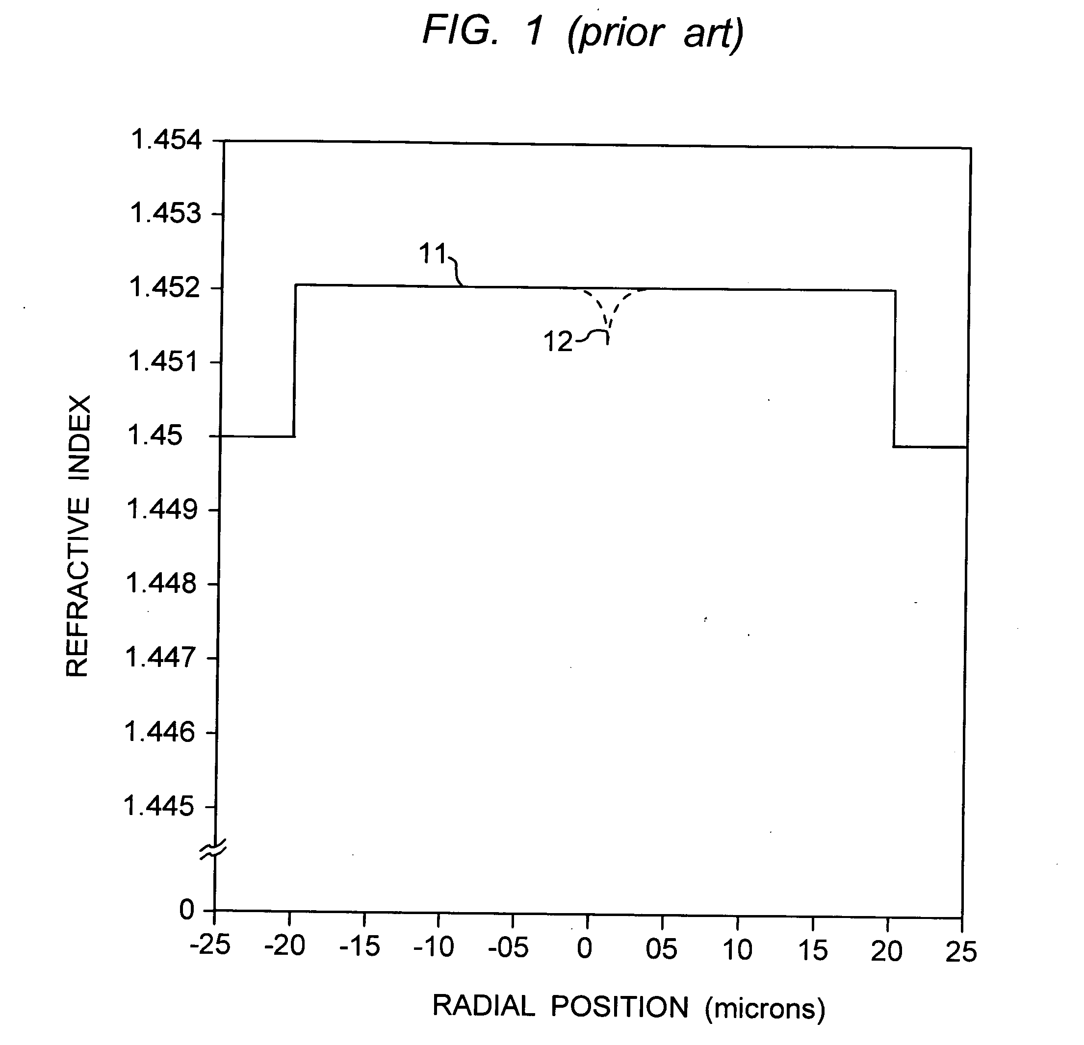
[0012]FIG. 1 shows a refractive index profile 11 for a conventional large mode area step index fiber. The plot is refractive index vs. radial position, and is idealized for the purpose of the description and analysis presented here. The core is typically Ge doped to an index value of approximately 1.452. The cladding shown here is pure silica with a nominal index of 1.45. The focus of these figures and this discussion is the core of the optical fiber. A wide variety of cladding structures, having un-doped layers, down-doped trench layers, up-doped layers for microbending control etc. may be used with the core structures described here.

[0013]FIG. 1 shows a large core, approximately 40 microns in diameter (with a fundamental LP01 modal effective area of approximately 750 μm2 around 1 μm wavelength). The large core serves to spread the modefield of the optical pulse and maintain the intensity below the threshold for damage.

[0014]However, as discussed above, even large core fibers like ...


PUM


Abstract

The specification describes optical fiber designs that overcome the problem of self-induced damage to optical fibers due to excessive self-focusing. The refractive index of these fiber designs is grossly non-uniform in the center core of the optical fiber. In one embodiment, the optical fiber is designed with a deliberate and steep core trench. In addition, the nominal core region of these optical fibers has a very large area. The combination of these two properties restricts a large portion of the optical power envelope to a core ring, with reduced optical power inside the core ring. These designs substantially reduce self-focusing in the optical fiber. Photonic systems employing optical fibers having these modified core designs are expected to be especially effective for transmitting high power, e.g., greater than 1 MW, with short pulse duration.

Description

FIELD OF THE INVENTION [0001]This invention relates to optical fibers that are specially designed to carry high optical power.BACKGROUND OF THE INVENTION [0002]At very high powers (approximately >1 MW) an optical beam increases the refractive index of the silica glass by an amount proportional to the local intensity. This can create a lens that focuses the beam down to a small spot (or a collection of small spots) causing optical damage. This process is termed self-focusing and has been extensively studied over the past several decades. (See R. W. Boyd, Nonlinear Optics, 2nd. Edition, Academic Press, Boston, 2003.) Self-focusing serves as an upper limit on the maximum power that can be guided in materials such as silica glass, and this limit is often termed the critical power for self focusing, Pcrit, which according to Fibich et al. (G. Fibich and A. L. Gaeta, “Critical power for self-focusing in bulk media and in hollow waveguides,”Optics Leffers, vol. 25, pp. 335-337 (2000)) c...

Claims


Application Information

Patent Timeline
IPC IPC(8): G02B6/02
CPCG02B6/02009G02B6/02019G02B6/4296G02B6/03611G02B6/032
Inventor DIGIOVANNI, DAVID J.JASAPARA, JAYESHYABLON, ANDREW D.
Owner FURUKAWA ELECTRIC CO LTD
Why Eureka
Try Eureka