
Fiber optic temperature sensing system using a hemispherical phosphor

a temperature sensing system and fiber optic technology, applied in the field of temperature sensing, can solve the problems of preventing the efficient utilization of excitation light, affecting the efficiency of excitation light, and mechanical stability of construction, and achieves enhanced fluorescence signal, enhanced absorption, and enhanced fluorescence signal.

Inactive Publication Date: 2008-03-20
DJEU DEREK
View PDF14 Cites 10 Cited by
  • Summary
  • Abstract
  • Description
  • Claims
  • Application Information

AI Technical Summary

Benefits of technology

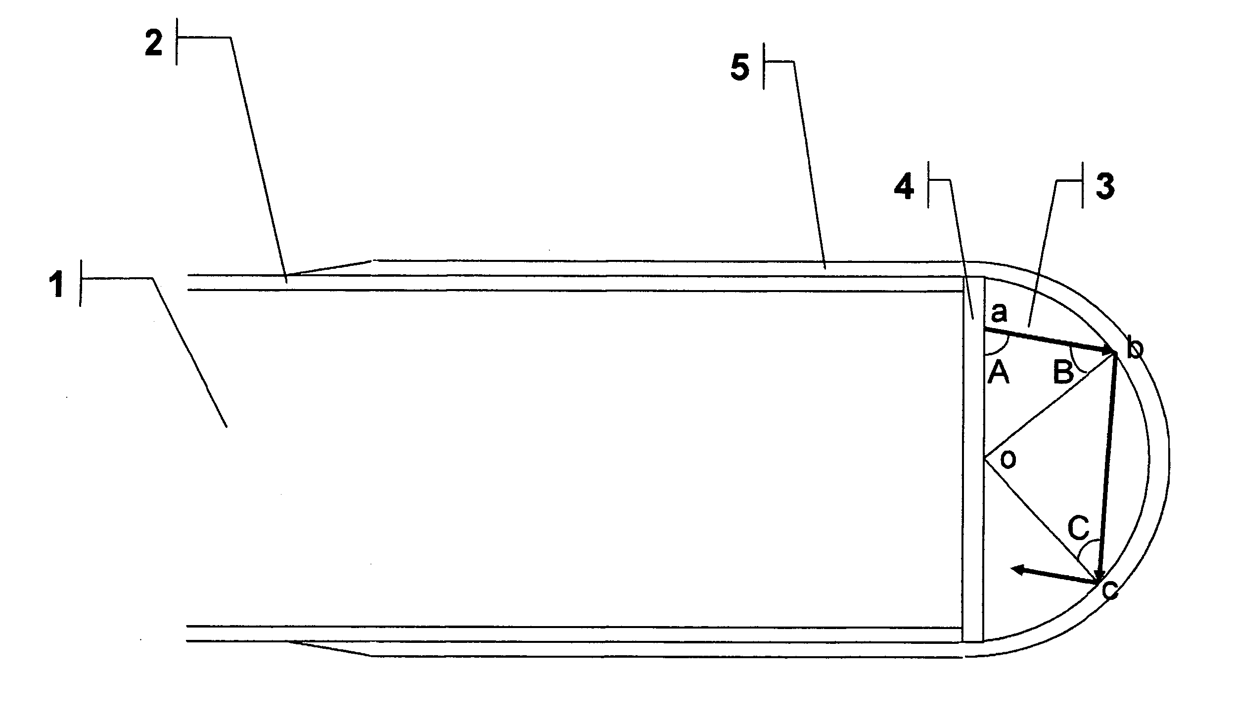
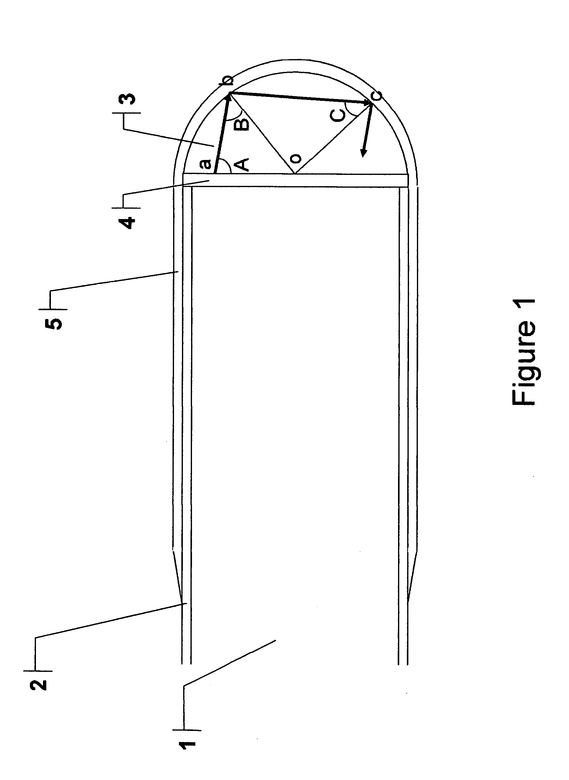
[0007]This invention provides a fiber optic temperature sensing system employing a probe with a substantially hemispherical phosphor. With such a construction, some of the excitation light rays experience multiple total internal reflections within the phosphor, which leads to increased absorption. Furthermore, some of the fluorescence which would otherwise exit the phosphor through its front surface will be directed back into the fiber, also as a result of total internal reflection. Both of these effects lead to an enhanced fluorescence signal. A hemispherically shaped phosphor also facilitates the creation of a robust bond between the phosphor and the fiber.
[0008]The fabrication of such a probe consists of two steps. First, the hemispherical phosphor is attached to the polished end of a lead fiber using either a wetting agent or an adhesive with good transparency. The bonding achieved in this first step needs only to be strong and lasting enough so that the phosphor does not fall off in the second step, which consists of dipping the assembled phosphor and fiber in a second adhesive to provide a coating with permanent bonding ability surrounding the hemispherical phosphor and the end portion of the lead fiber. This second step may be repeated to create a more robust structure if necessary. Preferably, the second adhesive should be diffusively reflective when fully cured to enhance both the absorption of the excitation light and the collection of the fluorescence.

Problems solved by technology

This construction, however, is not very stable mechanically.
While this latter phosphor attachment method is mechanically robust, its manufacture is very time-intensive.
This short length often prevents the efficient utilization of the excitation light if the absorption in the phosphor is not strong enough.

Method used


Image

  • Fiber optic temperature sensing system using a hemispherical phosphor
  • Fiber optic temperature sensing system using a hemispherical phosphor
  • Fiber optic temperature sensing system using a hemispherical phosphor

Examples


Embodiment Construction

[0015]A preferred way of fabricating the hemispherical phosphor is to start with a microsphere having a radius approximately equal to that of the fiber to which it is to be attached. It is then polished until approximately half is left. It should be clear to those versed in the art that hemispherical phosphors with the same radius can be fabricated in batches in this fashion.

[0016]With the phosphor lying on a flat surface with its curved side facing up, it can be picked up by a suction capillary tube. The tube is then oriented so that the end holding the phosphor is pointing up, and the vacuum is turned off. Next the polished end of an optical fiber is dipped in a liquid, held with the wetted end facing down, centered directly above the flat side of the phosphor, and lowered to make contact with the phosphor. Provided the liquid wets both the fiber and the phosphor, the phosphor will be held to the fiber at least temporarily. This bond needs only to be strong enough so that the phos...


PUM

PropertyMeasurementUnit
fluorescenceaaaaaaaaaa
radiusaaaaaaaaaa
lengthaaaaaaaaaa

Abstract

The present invention provides a fluorescence-based fiber optic temperature sensing system employing a probe with a hemispherically shaped phosphor attached thereto. The probe set forth herein not only produces fluorescence efficiently, but is also easily fabricated.

Description

REFERENCE TO RELATED APPLICATION[0001]This application claims the benefit of U.S. Provisional Patent Application No. 60 / 845,820 filed on Sep. 19, 2006.FIELD OF INVENTION[0002]This invention relates generally to a means of temperature sensing and, more particularly, a means of temperature sensing using an optical fiber with a phosphor attached to its end.BACKGROUND OF INVENTION[0003]Fiber optic temperature sensors based on the fluorescence from phosphors are widely used in electrically or RF / microwave noisy environments. Typically, excitation light is guided by the optical fiber to the phosphor sensing element. The temperature of the latter is manifested through its fluorescent properties, such as changes in its emission spectrum or decay time. Once the fluorescence signal is guided back by the fiber and processed, a correlation with the temperature can be made.[0004]The attachment of the phosphor sensing tip to the optical fiber can take many forms. An early proposal was to use an e...

Claims


Application Information

Patent Timeline
Patent Type & Authority Applications(United States)
IPC IPC(8): G01K11/00
CPCG01K11/3213
Inventor DJEU, DEREK
Owner DJEU DEREK
Learn More