This helps you quickly interpret patents by identifying the three key elements:
Problems solved by technology
Method used
Benefits of technology
[0008]The present invention has been made in the light of the above-mentioned problems, and provides an organic light-emitting device in which, while a chromaticity difference due to the view angle of an organic light-emitting element is suppressed, resonance is intensified so that an improvement in entire luminous efficiency can be achieved.
[0012]According to the present invention, an organic light-emitting element can be provided with an optimum micro cavity structure. As a result, while a chromaticity difference due to a view angle is suppressed, resonance is intensified, and hence an improvement in entire luminous efficiency can be achieved.
[0013]In particular, when materials for the semi-transparent layers of all or a part of organic light-emitting elements are different from each other, a thickness between both electrodes of each of the organic light-emitting elements can be made large, so that robustness based on a thickness variation is improved. As a result, an organic light-emitting device having characteristics with less fluctuation in production thereof can be provided.
Problems solved by technology
Accordingly, an organic light-emitting element having a relatively low intensity of resonance involves a problem that the luminous efficiency of the element cannot be sufficiently improved.
In addition, an organic light-emitting device has a serious problem of a chromaticity difference due to a view angle, and the more intense the resonance, the larger a view angle difference.
Method used
Image
Click on the blue label to locate the original text in one second.
Reading with bidirectional positioning of images and text.
Examples
first embodiment
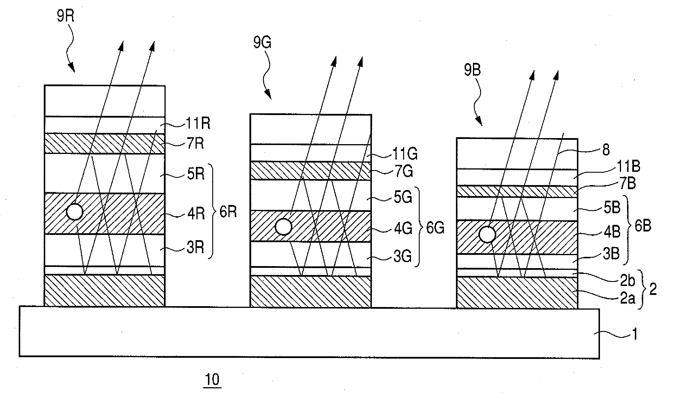
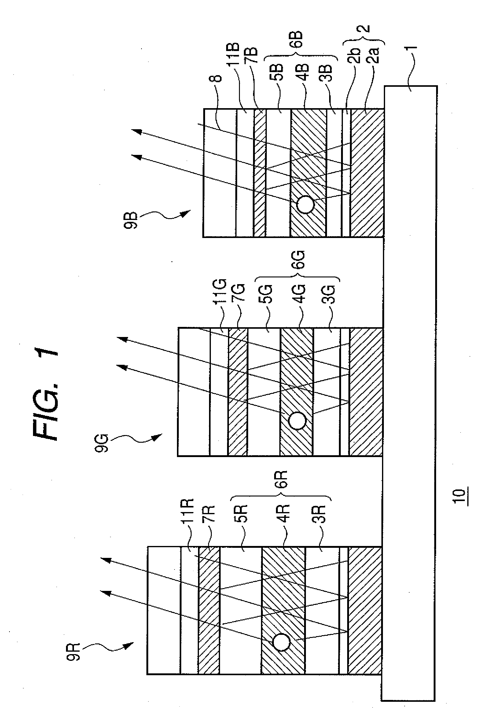
[0025]FIG. 1 is a partially enlarged sectional view illustrating an example of the constitution of an organic light-emitting device according to the present invention.
[0026]An organic light-emitting device 10 shown in FIG. 1 is an organic light-emitting device having organic light-emitting elements 9R, 9G and 9B showing red (R), green (G) and blue (B) emission colors, respectively, and all organic light-emitting elements each have a micro cavity structure.
[0027]Each of the organic light-emitting elements 9R, 9G and 9B has such a constitution that a first electrode 2 having a reflective surface as an anode, a hole transport layer 3R, 3G or 3B, a light-emitting layer 4R, 4G or 4B, and an electrontransport layer 5R, 5G or 5B as an organic compound layer 6R, 6G or 6B, a semi-transparent layer 7R, 7G or 7B as a cathode, a transparent conductive layer 11R, 11G or 11B, and a protective layer 8 are sequentially provided on a substrate 1. The organic light-emitting device is of a top emissi...
second embodiment
[0045]In first Embodiment, the thickness of the semi-transparent layers 7R, 7G and 7B was determined in order that an organic light-emitting element for each color might have the maximum efficiency. However, when an organic light-emitting device is considered to be a display device, not only luminous efficiency but also a view angle characteristic is extremely important. In general, the view angle characteristic of an organic light-emitting element using a micro cavity structure deteriorates as resonance is intensified. To be specific, as the semi-transparent layer of the element is made thicker, a chromaticity difference due to a view angle becomes larger. In view of the foregoing, in this embodiment, an organic light-emitting device taking not only luminous efficiency but also a view angle characteristic in consideration is provided.
[0046]In order to obtain a good view angle characteristic, in all organic light-emitting elements on an organic light-emitting device, a chromaticity ...
third embodiment
[0050]An organic light-emitting device of this embodiment has the same constitution as that of first Embodiment except that a material for the semi-transparent layer 7B of the organic B light-emitting element having the worst luminous efficiency is changed.
[0051]To be specific, both the semi-transparent layers 7R and 7G are each formed of a silver film having a thickness of 10 nm, and the semi-transparent layer 7B is formed of an aluminum film having a thickness of 10 nm.
PUM
Abstract
The organic light-emitting device of the present invention includes a plurality of organic light-emitting elements including an organic light-emitting element showing a first emission color and at least one organic light-emitting element showing a different emission color from the first emission color, each of the organic light-emitting elements including: a first electrode having a reflective surface; a second electrode placed on a light extraction side and including a semi-transparent layer; an organic compound layer including a light-emitting layer and formed between the first electrode and the second electrode; and a micro cavity structure for resonating light emitted from the light-emitting layer between the reflective surface and the semi-transparent layer, wherein the semi-transparent layer in the organic light-emitting element showing the first emission color is different in thickness and / or material from the semi-transparent layer in the at least one organic light-emitting element showing the different emission colors.
Description
BACKGROUND OF THE INVENTION[0001]1. Field of the Invention[0002]The present invention relates to an organic light-emitting device provided with a plurality of organic light-emitting elements different from each other in emission color.[0003]2. Description of the Related Art[0004]Organic light-emitting elements (organic electroluminescence elements) have been actively researched and developed these days. An organic light-emitting element involves the following problems: the securement of a color purity and an improvement in luminous efficiency. One known solution to the problems is a micro cavity structure in which an electrode on a light extraction side is made semi-transparent so that light emitted from a light-emitting layer is resonated between both electrodes.[0005]For example, International Patent Publication No. WO 01 / 039554 discloses a display device in which a light-emitting layer is interposed between a first electrode formed of a light reflection material and a second elec...
Claims
Application Information
Patent Timeline
Application Date:The date an application was filed.
Publication Date:The date a patent or application was officially published.
First Publication Date:The earliest publication date of a patent with the same application number.
Issue Date:Publication date of the patent grant document.
PCT Entry Date:The Entry date of PCT National Phase.
Estimated Expiry Date:The statutory expiry date of a patent right according to the Patent Law, and it is the longest term of protection that the patent right can achieve without the termination of the patent right due to other reasons(Term extension factor has been taken into account ).
Invalid Date:Actual expiry date is based on effective date or publication date of legal transaction data of invalid patent.