
System and Method for Detecting the Presence of a Threat in a Package

Inactive Publication Date: 2008-03-13
VOTI INC
View PDF3 Cites 20 Cited by
  • Summary
  • Abstract
  • Description
  • Claims
  • Application Information

AI Technical Summary

Benefits of technology

[0013] In yet other embodiments of the invention, the information related to the absorption of X-rays is encoded in a single number or string of characters. In these embodiments of the invention, it may be simpler to detect whether a specific threat detection criterion is satisfied or not. Also, such an encoding allows the production of proprietary databases including predetermined threat signatures. Advantageously, the method allows the identification of a substance included in the package. Also, in some embodiments of the invention, determining if the specific threat detection criterion is satisfied it is relatively easy and relatively fast to perform. This allows scanning packages for threat at relatively large throughputs.
[0014] In some embodiments of the invention, the method is performed entirely automatically by a computer so as to reduce the need to have relatively specialized security personnel performing a relatively monotonous task.

Problems solved by technology

However, users of currently used systems are often rather novice at this task and may therefore fail to detect many potential threats.
In addition, it is often the case that very few threats are effectively present in the scanned objects, which may lead to lack of attention from the user who has to look at images of non-threatening objects for many consecutive hours.
In addition, it may be relatively hard for the user to identify combinations of unassembled or harmless substances contained into the object that may represent a danger in the event that they could be assembled or mixed together.
Compounding all these problems, currently used X-ray systems typically do not allow to identify the chemical composition of items within the object.
Therefore, dangerous chemicals, such as for examples explosives or biological agents, contained within a container located within the object are often not detected using X-ray systems.

Method used


Image

  • System and Method for Detecting the Presence of a Threat in a Package
  • System and Method for Detecting the Presence of a Threat in a Package
  • System and Method for Detecting the Presence of a Threat in a Package

Examples


Embodiment Construction

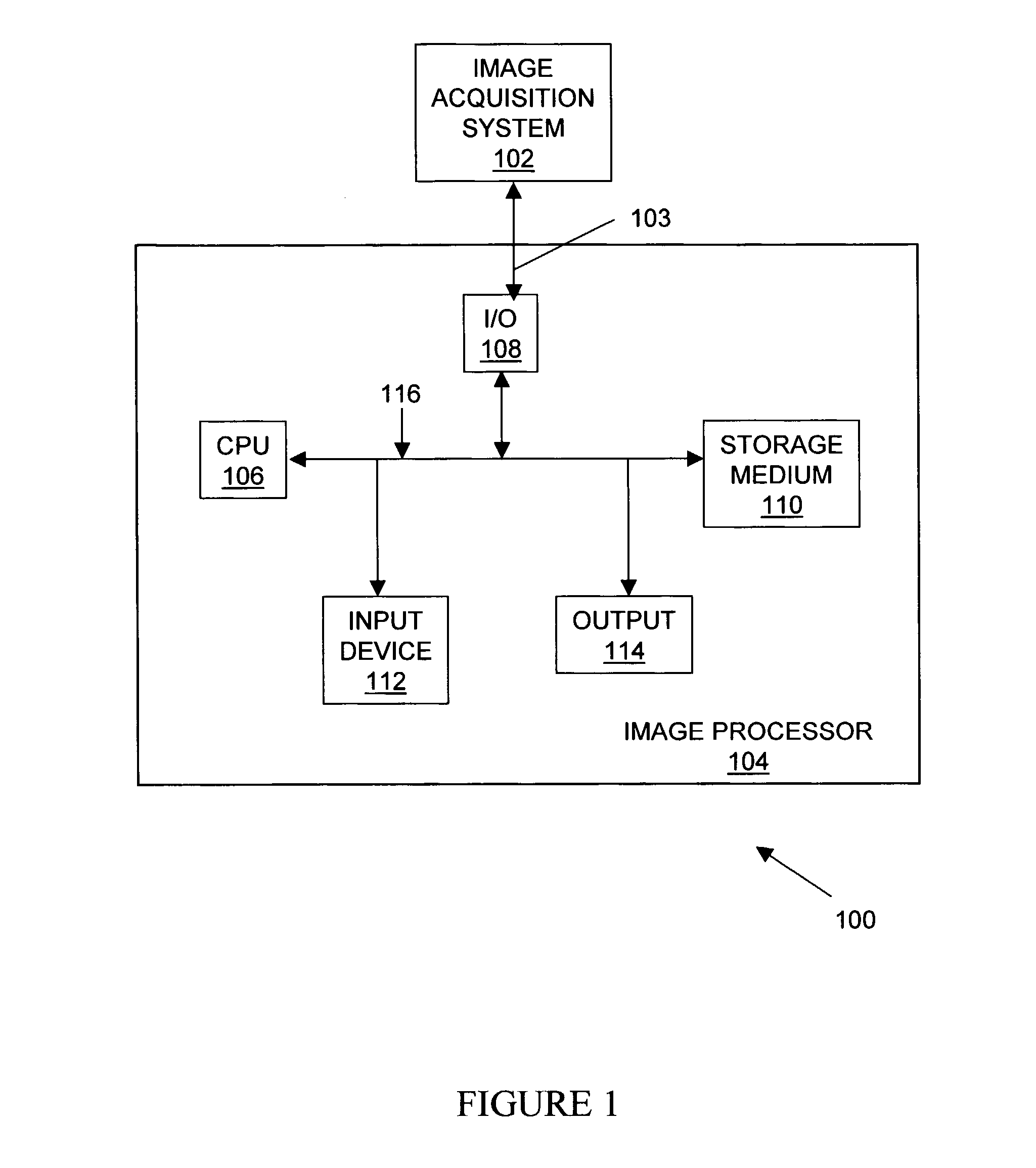
[0029]FIG. 1, in a schematic view, illustrates a threat detection system 100. The threat detection system 100 includes an image acquisition system 102 and an image processor 104 linked to the image acquisition system 102 by a communication link 103. The communication link 103 is any suitable communication link, such as for example and non-limitatively, a bus, an electrical serial link, an electrical parallel link, an optical fiber, a network, an infrared link or a radio link, among others.

[0030] The threat detection system 100 allows detecting the presence of a threatening object in a package 124 (shown in FIG. 2). Although the image acquisition system 102 and the image processor 104 are shown separately in FIG. 1, the reader skilled in the art will readily appreciate that these two components of the threat detection system 100 are either provided in separate devices or included within a single device in specific embodiments of the invention.

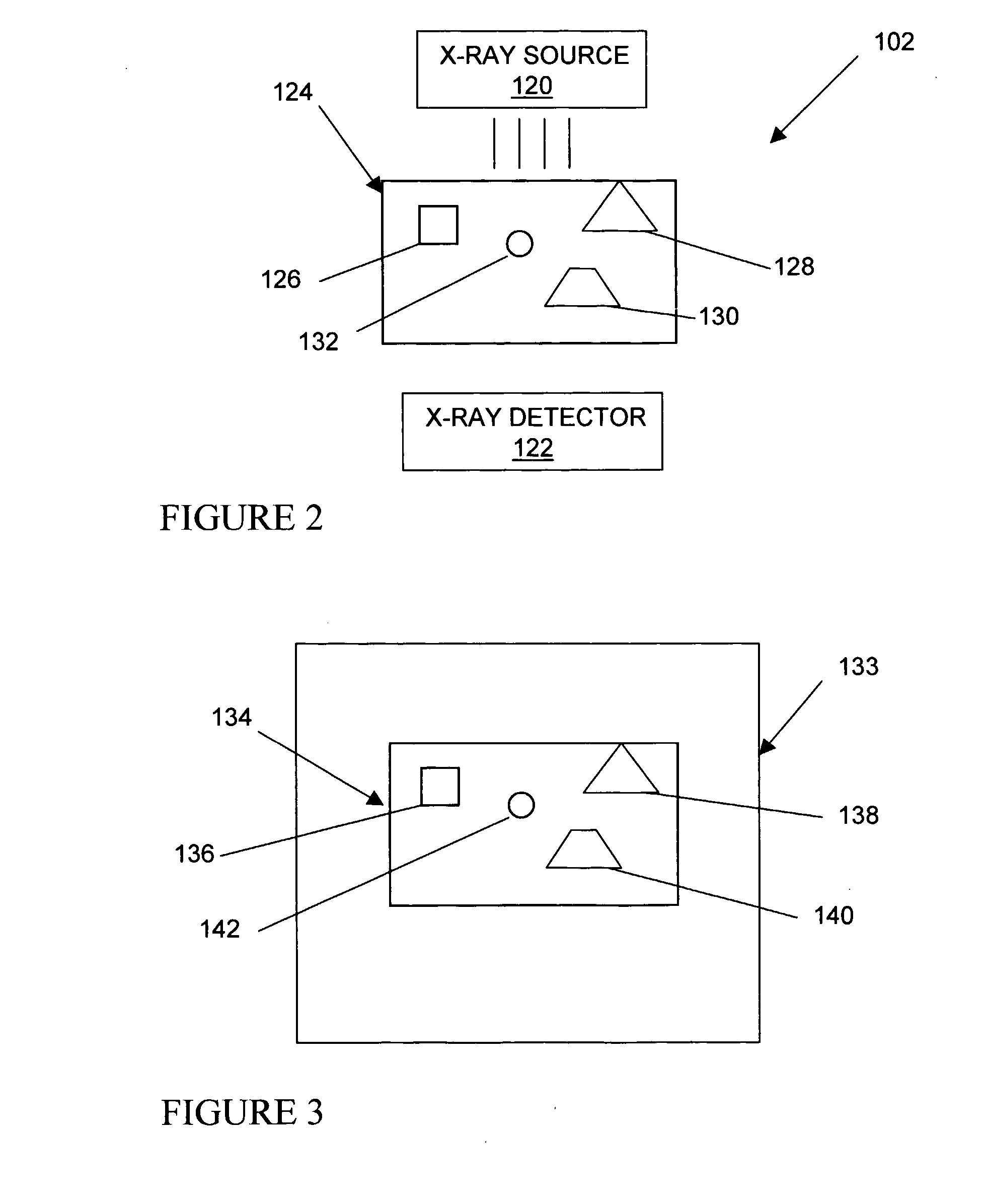
[0031] As shown schematically in FIG. 2...


PUM


Abstract

A method for scanning an object for potential threats. The method includes steps obtaining a plurality of stereographic colored X-ray images of the object, combining the plurality of stereographic images to produce a tridimensional model of the object, classifying each voxel from the tridimensional model into a predetermined material class indicative of a type of material included at a physical location modeled by the voxel, segmenting the tridimensional model using the intensity values and material classes associated with the voxels, thereby producing a segmented model including a plurality of object sub-components classifying each of the object sub-components included in the segmented model into a threat class, and issuing an alert signal upon a detection of an object subcomponent classified into a threatening class.

Description

[0001] This application claims priority from U.S. Provisional Patent Applications Ser. No. 60 / 588,999 filed Jul. 20, 2004.FIELD OF THE INVENTION [0002] The present invention relates to the general field of remote sensing. More specifically, the present invention is concerned with a system and a method for detecting the presence of a threat in a package. BACKGROUND OF THE INVENTION [0003] Security systems for X-ray scanning of objects are used at many locations, for example in airports. Typically, an object, such as for example a package or a piece of luggage, is scanned by X-rays to produce and image that is thereafter displayed on a monitor. Then, a user attempts to visually determine whether or not a threat is present within the object. For example, the user looks for the presence in the image of a shape similar to the shape of a gun or of a knife, among others. [0004] The efficiency of such systems depends on the proficiency and awareness of the user. However, users of currently ...

Claims


Application Information

Patent Timeline
IPC IPC(8): G01N23/04
CPCG01N23/04
Inventor AWAD, WILLIAM
Owner VOTI INC
Learn More