
Output terminal structure of alternator for vehicle

a technology for output terminals and alternators, applied in the field of alternators, can solve the problems of output terminals rotating undesired, deformation of radiator fins, increase production steps, etc., and achieve the effects of increasing the rigidity and reducing the deformation of positive-side radiator fins

Inactive Publication Date: 2008-03-13
DENSO CORP
View PDF8 Cites 2 Cited by
  • Summary
  • Abstract
  • Description
  • Claims
  • Application Information

AI Technical Summary

Benefits of technology

The invention is an alternator for vehicles that has a structure improved to avoid deformation of a radiator fin and undesirable rotation of an output terminal, ensuring stability of electric connection between the output terminal and a harness of a vehicle. The alternator includes a stator winding, a rotor working to induce ac voltage at the stator winding, a rectifier including a positive and negative rectifying device to rectify the ac voltage, a frame on which the rectifier is installed, a positive-side radiator fin in which the positive rectifying device is installed, an output terminal through which the dc voltage, as produced by the rectifier, is outputted, and first and second protrusions formed on the positive-side radiator fin across the through hole of the output terminal. The first and second protrusions serve as stoppers on which two corners of the output terminal hit to hold the output terminal from rotating undesirably, minimizing deformation of the positive-side radiator fin. The positive-side radiator fin has a first wall on which the positive rectifying device is installed and a second wall in which the through hole is formed, and the first and second protrusions are ribs extending perpendicular to both walls, resulting in an increase in rigidity of the positive-side radiator fin which increases resistance to deformation. The head of the output terminal is of a rectangular shape, facilitating the function of the protrusions as the stoppers. The positive-side radiator fin is made by die-casting aluminum, facilitating the formation of the protrusions into a desired shape. The alternator may further include a terminal table in which connector terminals are embedded in electric connections with the positive and negative rectifying devices of the rectifier.

Problems solved by technology

The above alternator, however, has the drawback in that installation of the output terminal in the positive-side radiator fin requires a high degree of accuracy in positioning thereof, thus resulting in an increase in production steps.
Thus, when an output conductor of the vehicle is joined or fastened to the output terminal, it will cause mechanical stress to concentrate on a portion of the head of the output terminal, which may result in deformation of the radiator fin.
The excessive deformation of the radiator fin may permit the output terminal to rotating undesirably.

Method used


Image

  • Output terminal structure of alternator for vehicle
  • Output terminal structure of alternator for vehicle
  • Output terminal structure of alternator for vehicle

Examples


Embodiment Construction

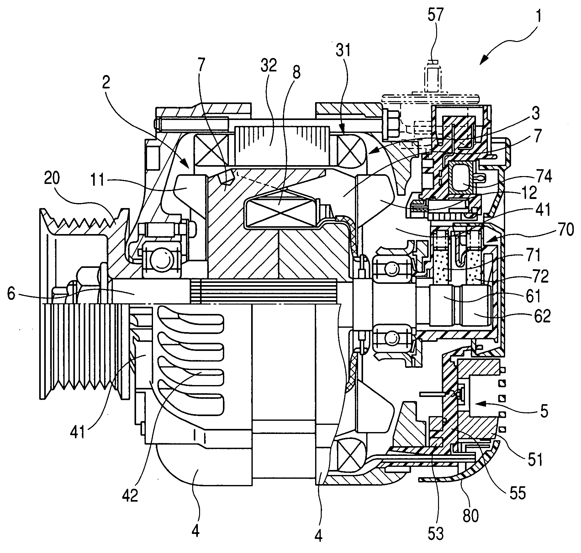
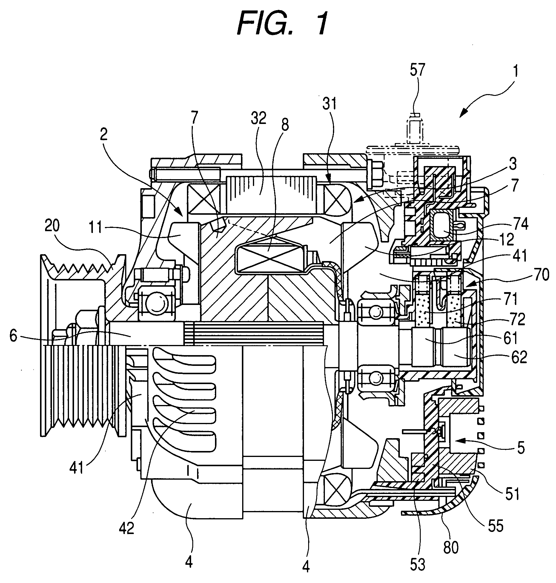
[0023]Referring to the drawings, wherein like reference numbers refer to like parts in several views, particularly to FIG. 1, there is shown an AC generator or alternator 1 for automotive vehicles according to the first embodiment of the invention.

[0024]The alternator 1 consists essentially of a rotor 2, a stator 3, a frame assembly 4, and a rectifier 5.

[0025]The rotor 2 is, as clearly shown in FIG. 1, made up of a pair of Randel-type pole cores 7 with claws and a field coil 8 retained between the pole cores 7. The field coil 8 is made of copper wire which is coated with an insulator and wound coaxially in the form of a cylindrical shape. A rotating shaft 6 is inserted through the pole cores 7. A cooling fan 11 is welded to an end wall of a front one (i.e., a left one, as viewed in FIG. 1) of the pole cores 7. The cooling fan 11 works to suck air from the front of the alternator 1 and discharge it axially and radially of the alternator 1. Similarly, a centrifugal fan 12 is welded to...


PUM


Abstract

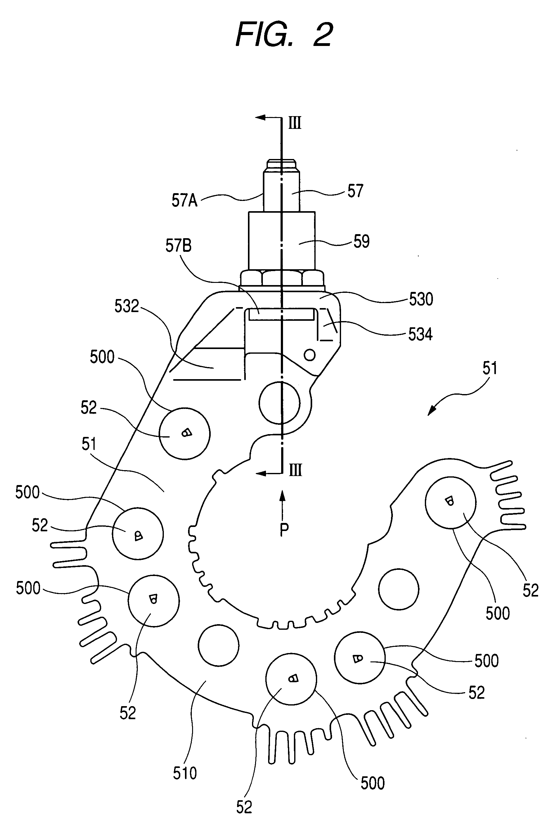
An alternator for a vehicle is provided which is equipped with a rectifier. The rectifier includes a positive-side radiator fin in which a positive rectifying device is installed. An output terminal through which dc voltage is outputted has a rectangular head and is fit in a through hole formed in the positive-side radiator fin. Ribs are formed on the positive-side radiator fin across the through hole. The rectangular head of the output terminal is shaped to have two sides and a diagonal line. The diagonal line is longer than an interval between the ribs. The sides are located at a distance away from each other which is smaller than the interval between the ribs. Specifically, the ribs serve as stoppers on which corners of the head hits when excessive torque acts on the output terminal, thereby minimizing deformation of the positive-side radiator fin and undesirable rotation of the output terminal.

Description

CROSS REFERENCE TO RELATED DOCUMENT[0001]The present application claims the benefit of Japanese Patent Application No. 2006-242712 filed on Sep. 7, 2006, the disclosure of which is incorporated herein by reference.BACKGROUND OF THE INVENTION[0002]1. Technical Field of the Invention[0003]The present invention relates generally to an alternator which may be installed in passenger automobiles or autotrucks, and more particularly to such an alternator designed to have a structure improved to avoid deformation of a radiator fin of a rectifier and undesirable rotation of an output terminal, and ensure the stability of electric connection between the output terminal and a harness of a vehicle.[0004]2. Background Art[0005]Typical automotive alternators are equipped with a rectifier which has a positive-side radiator fin and a negative-side radiator fin which extend perpendicular to a rotating shaft in order to decrease an axial length of the alternator and increase areas of the radiator fin...

Claims


Application Information

Patent Timeline
Patent Type & Authority Applications(United States)
IPC IPC(8): H02K19/36
CPCH02K11/046H02K5/225H02K11/05
Inventor KOIKE, AKIHITOTAN, YOSHIKIKOUMURA, MASATOSHI
Owner DENSO CORP
Learn More