
Fan and impeller thereof

a technology of a fan and an impeller, which is applied in the direction of liquid fuel engines, vessel construction, marine propulsion, etc., can solve the problems of time-consuming adjustment to achieve a rotational balance, hindering from rotational balance, and difficult to remove by the tool, so as to improve the stability of rotation and the reliability and lifespan of the fan

Inactive Publication Date: 2008-03-06
DELTA ELECTRONICS INC
View PDF9 Cites 39 Cited by
  • Summary
  • Abstract
  • Description
  • Claims
  • Application Information

AI Technical Summary

Benefits of technology

[0009]Impellers, improving the stability of the rotation and the reliability and lifespan of the fan, are provided.
[0010]To achieve the described purpose, an exemplary embodiment of an impeller includes a hub and a plurality of blades. The blades are disposed around the hub. An annular structure is connected to the blades. The annular structure and the hub are arranged concentrically. The annular structure has a plurality of apertures for filling in balance materials to achieve increasing balance when adjusting the rotational balance of the impeller.
[0011]To achieve the described purpose, the annular structure further includes at least one tooth in each of the apertures, the tooth can be removed by a tool to achieve decreasing balance when adjusting the rotational balance of the impeller without requiring balance materials to be filled in the apertures.
[0013]Furthermore, to achieve the described purpose, the aperture has a cross-section obliquely shaped along the centrifugal direction of the hub, and thus, the balance materials do not overflow the apertures during rotation.
[0015]Thus, rotational stability, reliability, and life span of the impeller of the fan are increased.

Problems solved by technology

When balance material is filled in the groove by a tool, however, it is difficult to remove by the tool since of the high-viscosity characteristic of the balance materials.
Thus, adjustment to achieve a rotational balance is time-consuming.
Additionally, balance materials may overflow from the groove during rotation of the impeller, hindering form the rotational balance.

Method used


Image

  • Fan and impeller thereof
  • Fan and impeller thereof
  • Fan and impeller thereof

Examples


Embodiment Construction

[0025]The following description is of the best-contemplated mode of carrying out the invention. This description is made for the purpose of illustrating the general principles of the invention and should not be taken in a limiting sense. The scope of the invention is best determined by reference to the appended claims.

[0026]An impeller is described with reference to the related drawings, wherein the same elements share the same references.

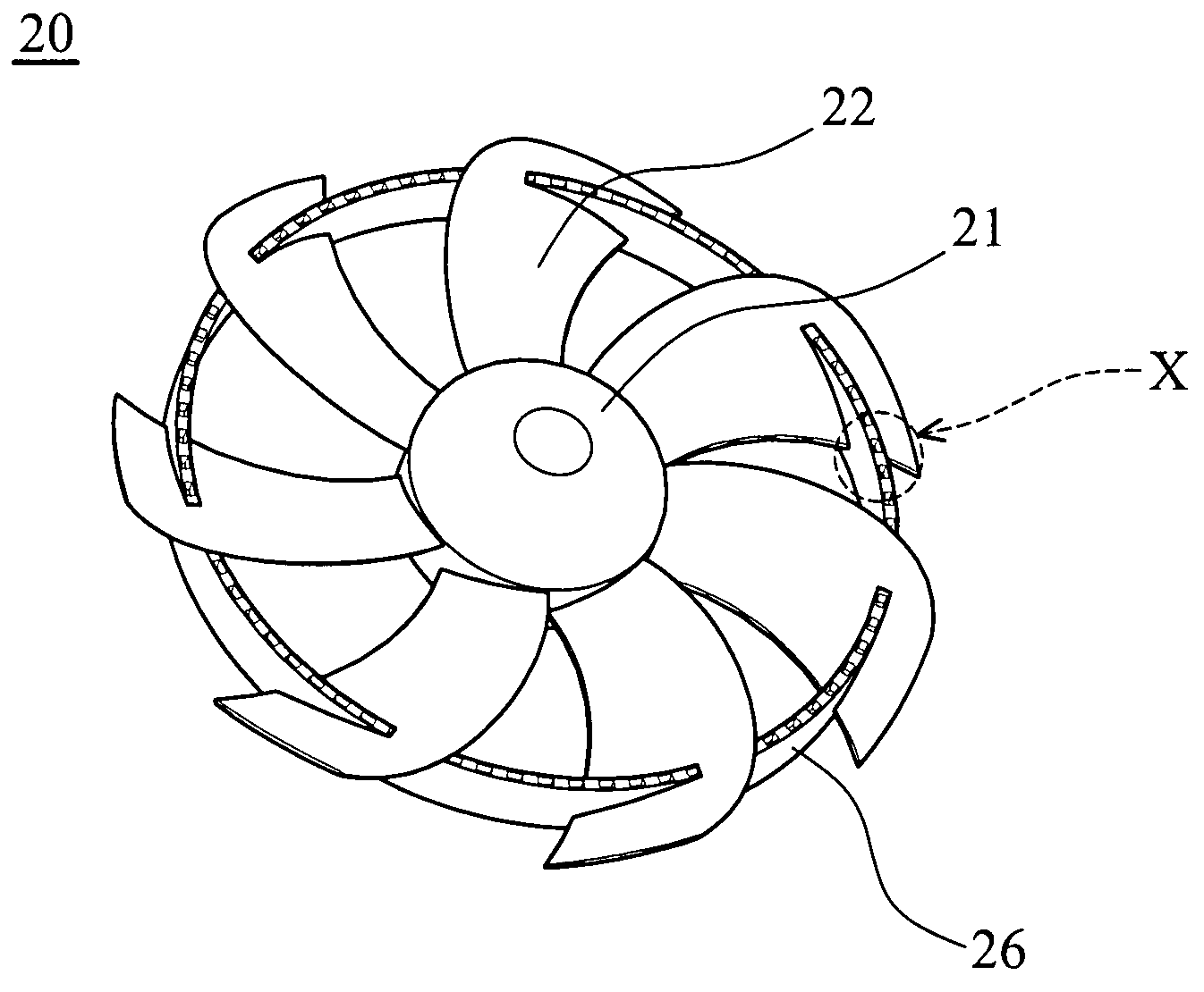
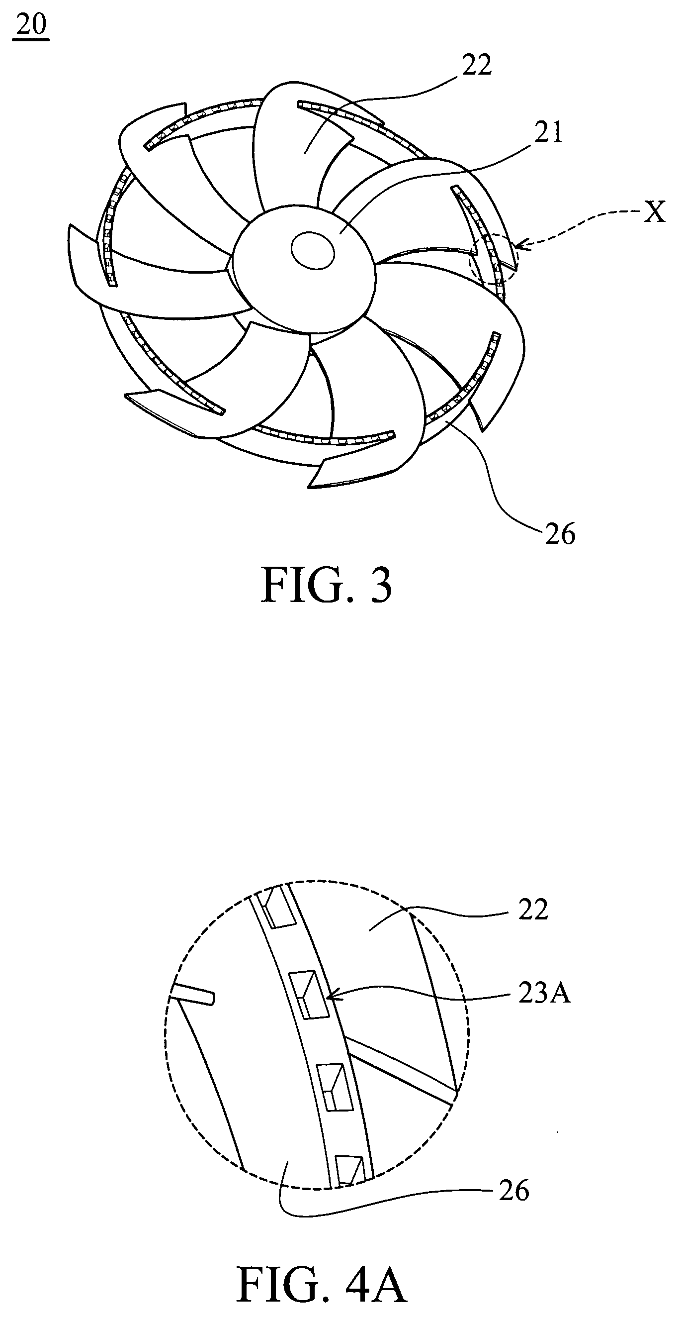
[0027]FIG. 3 is a schematic view of an embodiment of an impeller. The impeller 20 includes a hub 21 and a plurality of blades 22. The blades 21 are disposed around the hub 21. Each blade 22 is connected with an annular structure 26. The annular structure 26 and the hub 21 are arranged concentrically.

[0028]FIG. 4A is an enlarged view of X part of the impeller shown in FIG. 3. In FIG. 4A, an end surface of the annular structure 26 includes a plurality of the apertures 23A. Balance materials can be filled in the apertures 23A to achieve increasing bal...


PUM


Abstract

An impeller includes a hub, a plurality of blades, and an annular structure. The blades are disposed around the hub. The annular structure is connected to the blades. The annular structure includes a plurality of apertures. A balance material is filled in the apertures to achieve rotational balance of the impeller. Furthermore, a fan with the described impeller is provided. The fan and the impeller improve rotational stability, reliability and product life.

Description

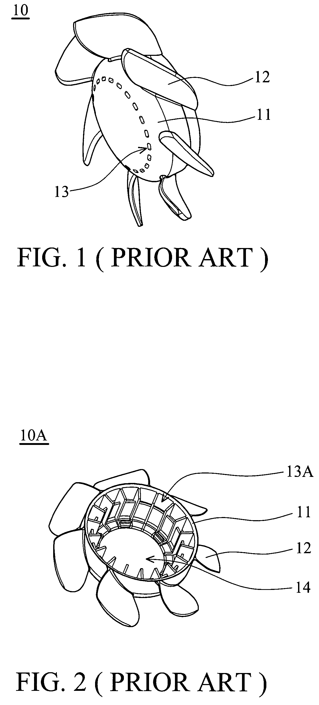
BACKGROUND OF THE INVENTION[0001]1. Field of the Invention[0002]The invention relates to a fan and an impeller thereof, and more particularly, to a fan and an impeller capable of stabilized rotational balance.[0003]2. Description of the Related Art[0004]Fans are widely utilized. A pressure difference of airflow occurs when the impeller of the fan rotates. Thus, the stabile impeller rotation is a basic requirement for all fans.[0005]A conventional fan includes an impeller and a motor for driving the impeller. As shown in FIG. 1, an impeller 10 includes a hub 11 and a plurality of blades 12 disposed around the hub 11. The hub 11 includes a plurality of grooves 13 for adjusting the impeller 10 during the rotating and shaking test. Thus, a suitable quantity of the balance material can be filled in the groove 13 for adjusting the rotational balance of the impeller 10.[0006]Subsequent to assembly of the hub and motor of another conventional impeller, a remainder space is necessary to fill...

Claims


Application Information

Patent Timeline
IPC IPC(8): F01D5/22
CPCF01D5/22F04D29/662F04D29/325F04D29/326
Inventor JIANG, CHEN-MOLAN, CHUNG-KAICHEN, HUNG-CHI
Owner DELTA ELECTRONICS INC
Learn More