Backlight driver, display apparatus having the same and method of driving backlight

a technology of display apparatus and backlight, which is applied in the direction of instruments, light sources, optics, etc., can solve the problems of deteriorating the image display quality on the lcd

Inactive Publication Date: 2008-03-06
SAMSUNG DISPLAY CO LTD
View PDF5 Cites 32 Cited by
  • Summary
  • Abstract
  • Description
  • Claims
  • Application Information

AI Technical Summary

Benefits of technology

[0010]In an exemplary embodiment of the present invention, a backlight driver includes an inverter controller, a dimming signal compensator and an inverter. The inverter controller generates a pulse width modulation signal in response to a control signal and outputs a first dimming signal that represents a duty ratio of the pulse width modulation signal and a second dimming signal that represents an amplitude of the pulse width modulation signal. The dimming signal compensator receives the first and second dimming signals and compares the first dimming signal with a predetermined reference duty ratio. The dimming signal compensator compensates the second dimming signal in accordance with the compared result to generate a third dimming signal. The inverter outputs a driving voltage to drive a backlight and varies a voltage level of the driving voltage in response to the first and third dimming signals to control a brightness of the backlight.
[0011]In an exemplary embodiment of the present invention, a display apparatus includes an inverter controller, a dimming signal compensator, an inverter a backlight and a display unit. The inverter controller generates a pulse width modulation signal in response to a control signal and outputs a first dimming signal that represents a duty ratio of the pulse width modulation signal and a second dimming signal that represents an amplitude of the pulse width modulation signal. The dimming signal compensator receives the first and second dimming signals and compares the first dimming signal with a predetermined reference duty ratio. The dimming signal compensator compensates the second dimming signal in accordance with the compared result to generate a third dimming signal. The inverter receives a power voltage and changes the power voltage into a driving voltage and varies a voltage level of the driving voltage in response to the first dimming signal and the third dimming signal. The backlight receives the driving voltage to generate light and the display unit displays an image using the light.
[0012]In an exemplary embodiment of the present invention, a method of driving a backlight includes receiving a first dimming signal that represents a duty ratio of a pulse width modulation signal and a second dimming signal that represents an amplitude of the pulse width modulation signal, comparing first dimming signal with a predetermined reference duty ratio, compensating the second dimming signal in accordance with the compared result to generate a third dimming signal, and receiving a power voltage to change the power voltage into a driving voltage for the backlight and varying a voltage level of the driving voltage in response to the first dimming signal and the third dimming signal to control a brightness of the backlight.

Problems solved by technology

However, since the current control method is not designed to control the brightness in a low current range, the PWM control method has been mainly used for illumination control of the CCFL of the LCD backlight.
In the PWM control method, however, the response speed of the backlight decreases in the range of a low duty ratio of the PWM signal while the backlight is being dimmed, and a brightness blurring phenomenon can occur, thereby deteriorating the image display quality on the LCD.

Method used


Image

  • Backlight driver, display apparatus having the same and method of driving backlight
  • Backlight driver, display apparatus having the same and method of driving backlight
  • Backlight driver, display apparatus having the same and method of driving backlight

Examples


Embodiment Construction

[0023]Hereinafter, exemplary embodiments of the present invention will be described in detail with reference to the accompanying drawings. Like reference numerals may refer to similar or identical elements throughout the description of the figures.

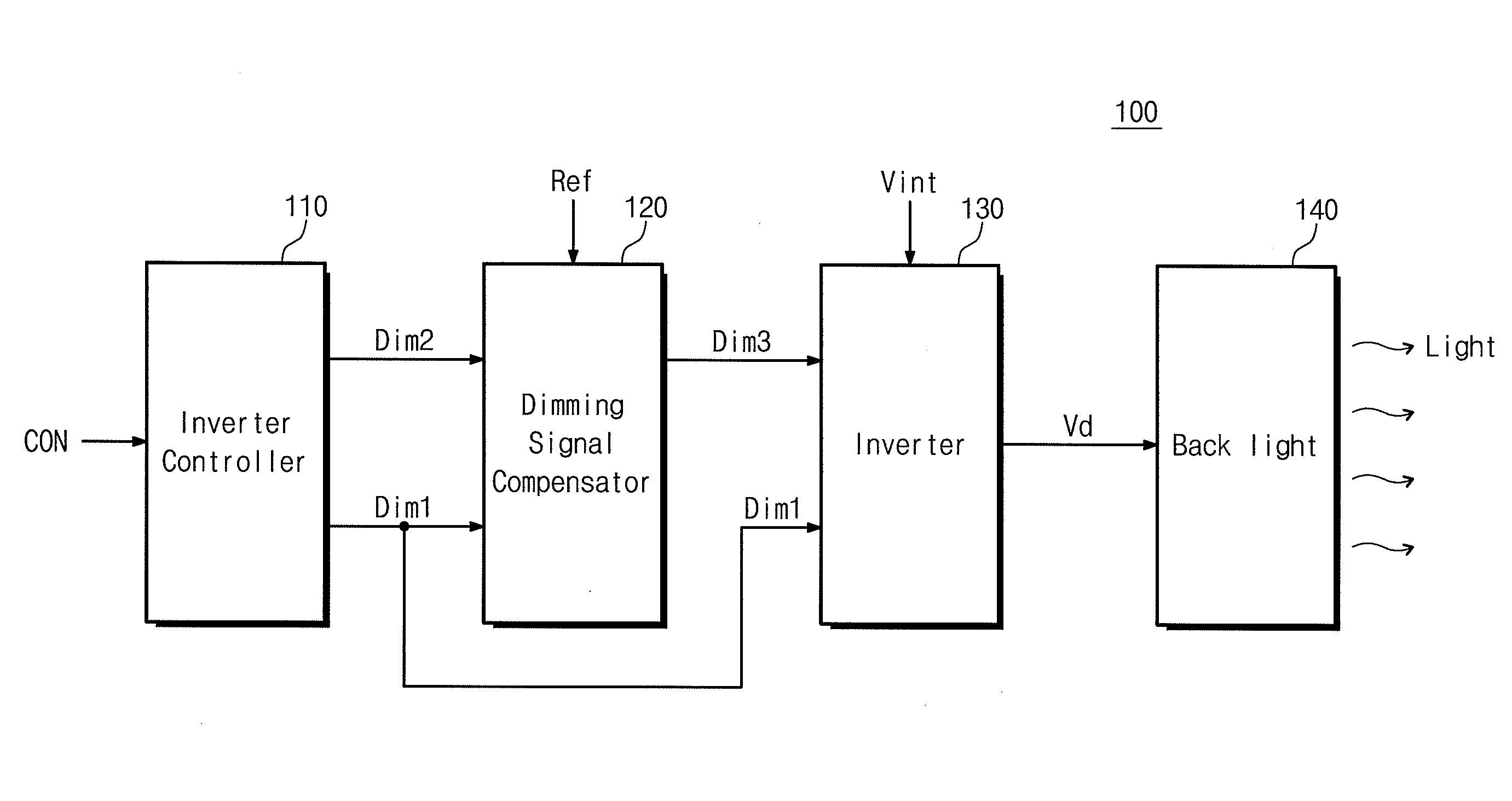
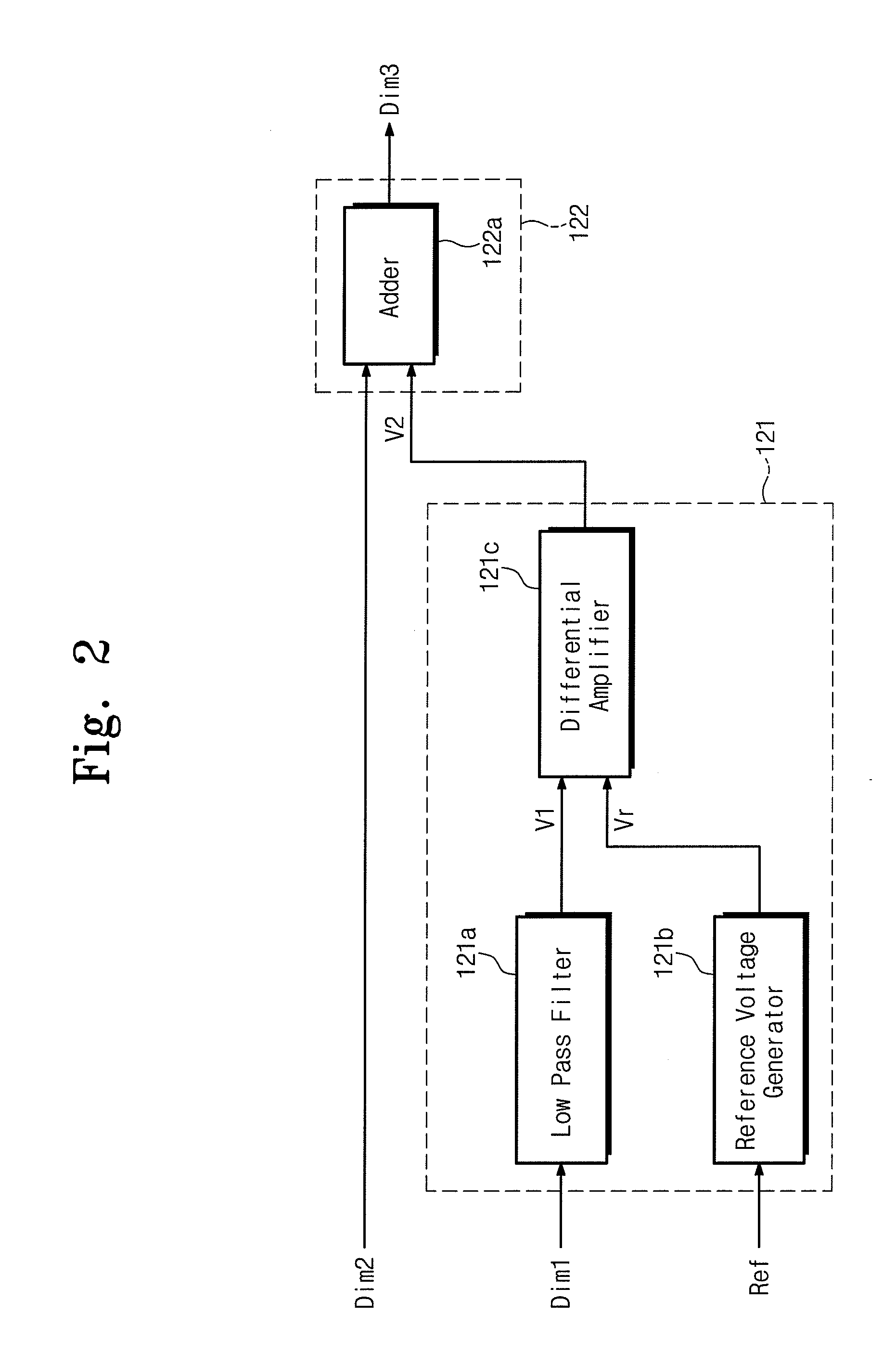
[0024]FIG. 1 is a block diagram showing a backlight driver according to an exemplary embodiment of the present invention. FIG. 2 is a block diagram of the dimming signal compensator of FIG. 1, according to an exemplary embodiment of the present invention.

[0025]Referring to FIG. 1, a backlight driver 100 drives a backlight 140 disposed at the rear of a display unit (not shown) for backlighting of the display unit. The backlight driver 100 includes an inverter controller 110, a dimming signal compensator 120 and an inverter 130.

[0026]The inverter controller 110 generates a pulse width modulation (PWM) signal in response to a control signal CON from an external source. The PWM signal may be generated to adjust the brightness of the backlight ...


PUM


Abstract

A backlight driver includes an inverter controller, a dimming signal compensator and an inverter. The inverter controller generates a pulse width modulation signal in response to a control signal and outputs a first dimming signal that represents a duty ratio of the pulse width modulation signal and a second dimming signal that represents an amplitude of the pulse width modulation signal. The dimming signal compensator receives the first and second dimming signals, compares the first dimming signal with a predetermined reference duty ratio and compensates the second dimming signal in accordance with the compared result to generate a third dimming signal. The inverter outputs a driving voltage to drive the backlight and varies a voltage level of the driving voltage in response to the first and third dimming signals to control a brightness of the backlight.

Description

CROSS-REFERENCE TO RELATED PATENT APPLICATION[0001]This application claims priority to Korean Patent Application No. 2006-82382, filed on Aug. 29, 2006, the contents of which are herein incorporated by reference in their entirety.BACKGROUND OF THE INVENTION[0002]1. Technical Field[0003]The present disclosure relates to a backlight driver, a display apparatus having the same and a method of driving the backlight. More particularly, the present disclosure relates to a backlight driver capable of improving the response speed of the backlight and stabilizing the brightness, a display apparatus having the backlight driver and a method of driving the backlight.[0004]2. Discussion of Related Art[0005]In general, a liquid crystal display (LCD) includes an LCD panel that is illuminated by a backlight. A cold cathode fluorescent lamp (CCFL) is commonly employed as the LCD backlight.[0006]Many applications require dimming capabilities, for example, to improve the contrast ratio of the display ...

Claims


Application Information

Patent Timeline
Patent Type & Authority Applications(United States)
IPC IPC(8): G09G3/36
CPCG09G3/2011G09G3/2014G09G2320/0252G09G3/3406G09G3/2081G02F1/133G02F1/1335H05B41/24H05B41/38
Inventor JANG, HYEON-YONGCHOI, SEONG-SIK
Owner SAMSUNG DISPLAY CO LTD
Why Eureka
Try Eureka