
System and Method for Displaying Computer Data in a Multi-Screen Display System

a multi-screen display and display system technology, applied in the direction of cathode-ray tube indicators, instruments, electric digital data processing, etc., can solve the problems of insufficient space in the laptop or notebook housing to accommodate more than one graphics port or graphics card

Inactive Publication Date: 2008-03-06
WILK RAYMOND RICHARD +1
View PDF5 Cites 65 Cited by
  • Summary
  • Abstract
  • Description
  • Claims
  • Application Information

AI Technical Summary

Benefits of technology

"This patent describes a system for displaying video data on multiple screens with different resolutions. The system includes multiple monitor controllers and a replicator. The replicator receives the video signal and replicates it to create multiple sets of video data. Each set of video data is sent to an associated monitor controller for processing. This results in images that appear to have a higher resolution than any individual screen. The system also includes a central controller that divides the video signal into multiple video streams, each sent to a different monitor for display. The technical effect of this patent is the ability to display video data on multiple screens with different resolutions using a single video source."

Problems solved by technology

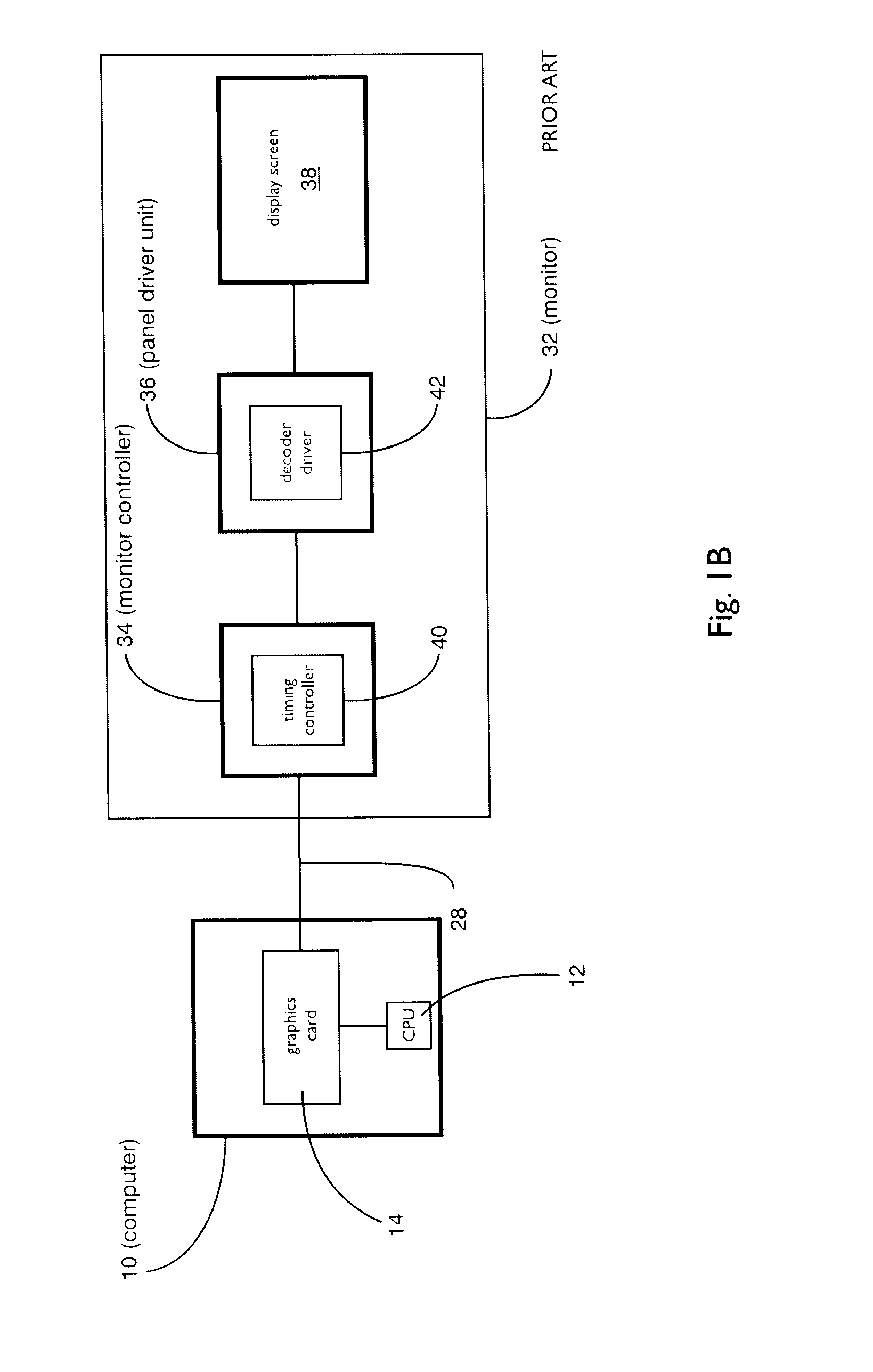
Although the potential uses for multi-screen display systems appear to be limited only by the user's imagination, a significant barrier arises when a user of a single-screen computer system wishes to upgrade to a multi-screen system.
However, in other systems, notably laptops or notebooks, there may not he enough space in the laptop or notebook housing to accommodate more than one graphics port or graphics card.
However, the use of such an extender is associated with some problems, such as compatibility issues between graphics card and laptop hardware.

Method used


Image

  • System and Method for Displaying Computer Data in a Multi-Screen Display System
  • System and Method for Displaying Computer Data in a Multi-Screen Display System
  • System and Method for Displaying Computer Data in a Multi-Screen Display System

Examples


example 1

[0042] Reference is now made to FIGS. 2, 3A, 3B and 4. FIG. 2 shows a block diagram of a computer system 100 having a computer 102, a multi-screen graphics apparatus 104, and a display system 106 having a first monitor 108 and a second monitor 110, in accordance with the principles of the present invention. FIGS. 3A, 3B and 4 respectively show the front and back of the display system 106, and a block diagram of the multi-screen graphics apparatus 104 of FIG. 2. The first monitor 108 includes a first screen 112 with a first native resolution, R1, and the second monitor 110 includes a second screen 114 with a second native resolution, R2. The computer 102 can include a laptop, notebook or PC having a central processing unit 116 and a graphics card 118. The display system 106 includes a base 120, an arm 122 for supporting the first monitor 108 and the second monitor 110, and a column 124 for connecting the base 120 to the arm 122. As described in detail below, the multi-screen graphics...

example 2

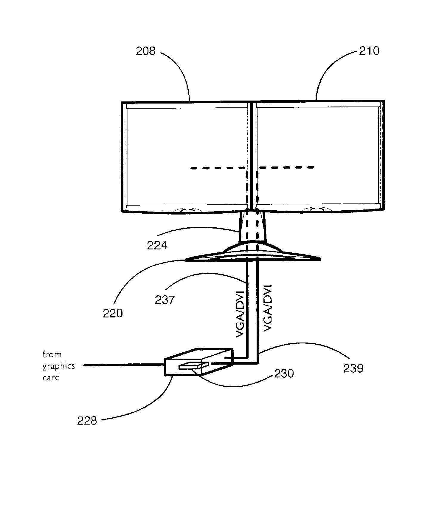
[0056] Reference is now made to FIGS. 5, 6A, 6B and 7. FIG. 5 shows a block diagram of a computer system 200 having a computer 202, a multi-screen graphics apparatus 204, and a display system 206 having first monitor 208 and a second monitor 210, in accordance with the principles of the present invention. FIGS. 6A, 6B and 7 respectively, show the front and back of the display system 206, and a block diagram of the multi-screen graphics apparatus 204 of FIG. 5. The first monitor 208 includes a first screen 212 with a first native resolution, and the second monitor 210 includes a second screen 214 with a second native resolution. The computer 202 can include a laptop, notebook or PC having a central processing unit 216 and a graphics card 218. The display system 206 includes a base 220, an arm 222 for supporting the first monitor 208 and the second monitor 210, and a column 224 for connecting the base 220 to the arm 222. The graphics card 218 is connected to the multi-screen graphics ...

example 3

[0070] Reference is now made to FIGS. 8, 9A, 9B and 10. FIG. 8 shows a block diagram of a computer system 300 having a computer 302, a multi-screen graphics apparatus 304, and a display system 306 having a first monitor 308 and a second monitor 310, in accordance with the principles of the present invention. FIGS. 9A, 9B and 10 respectively show the front and back of the display system 306, and a block diagram of the multi-screen graphics apparatus 304 of FIG. 8. The first monitor 308 includes a first screen 312 with a first native resolution. The first monitor 308 also includes a first end monitor controller 314 and a first panel driver unit 316. The second monitor 310 includes a second screen 318 with a second native resolution. The second monitor 310 also includes a second end monitor controller 320 and a second panel driver unit 322. The designation “end” is used in this example to distinguish the first and second monitor controllers 314 and 320 in the monitors from the first an...


PUM


Abstract

Described herein is a graphics apparatus for displaying video data on a display system having N monitors each containing a screen. The apparatus includes a central controller for receiving from a graphics card a video signal. The central controller divides at least a portion of the video signal into N video streams, each video stream sent to an associated one of the N monitors for producing images on the N screens.

Description

FIELD OF THE INVENTION [0001] The invention relates to multi-screen display systems, and more particularly to graphics and monitor control in such systems. BACKGROUND OF THE INVENTION [0002] The number of multi-monitor or multi-screen computer display systems has increased in recent years as computer users in various industries adapt their use to new environments. For example, a multi-screen display system can be used to create the illusion of a larger screen, thereby allowing a securities trader to view a large single spreadsheet over several displays. Alternately, the trader may view individual applications on individual screens (for example, one screen may display a Web browser, a second a new service and a third a spreadsheet of financial data). [0003] Individuals working with still or moving images, such as graphics artists, video or film editors, and medical diagnosticians may also use multi-screen display systems. A given image may be viewed across several screens, or two ima...

Claims


Application Information

Patent Timeline
Patent Type & Authority Applications(United States)
IPC IPC(8): G09G5/00
CPCG06F3/1431G09G2370/042G09G5/006G06F3/1446G09G5/00G09G5/12G09G5/14G06F3/1454
Inventor WILK, RAYMOND RICHARDTAMESHTIT, ALLAN
Owner WILK RAYMOND RICHARD
Learn More