
Dual action weightlifting machine

a dual-action, weightlifting technology, applied in the direction of gymnastic exercise, muscle exercise devices, sport apparatus, etc., can solve the problems of adding to the complexity and expense of the machine, but not as well, and achieve the effect of reducing wrist strain and duplicating the feel

Active Publication Date: 2008-02-28
HOIST FITNESS SYST
View PDF33 Cites 7 Cited by
  • Summary
  • Abstract
  • Description
  • Claims
  • Application Information

AI Technical Summary

Benefits of technology

The machine provides a safer, more versatile, and cost-effective means to perform a variety of exercises with reduced weight and complexity, allowing users to mimic free weight movements without the need for counterbalancing, enhancing user experience and reducing machine cost.

Problems solved by technology

This allows an exerciser to perform exercises with vertical up and down movement, such as squats, bench press exercises, and the like, but does not permit any horizontal movement.
These new designs worked better for exercises which involved travel in a slight arc, but not as well for other exercise motions which tended to follow a straight line.
It also adds to the complexity and expense of the machine.

Method used


Image

  • Dual action weightlifting machine
  • Dual action weightlifting machine
  • Dual action weightlifting machine

Examples


first embodiment

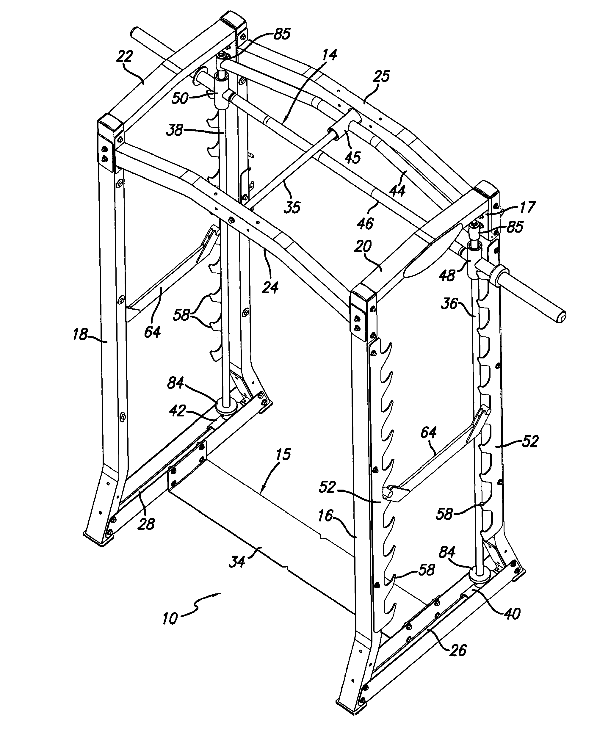
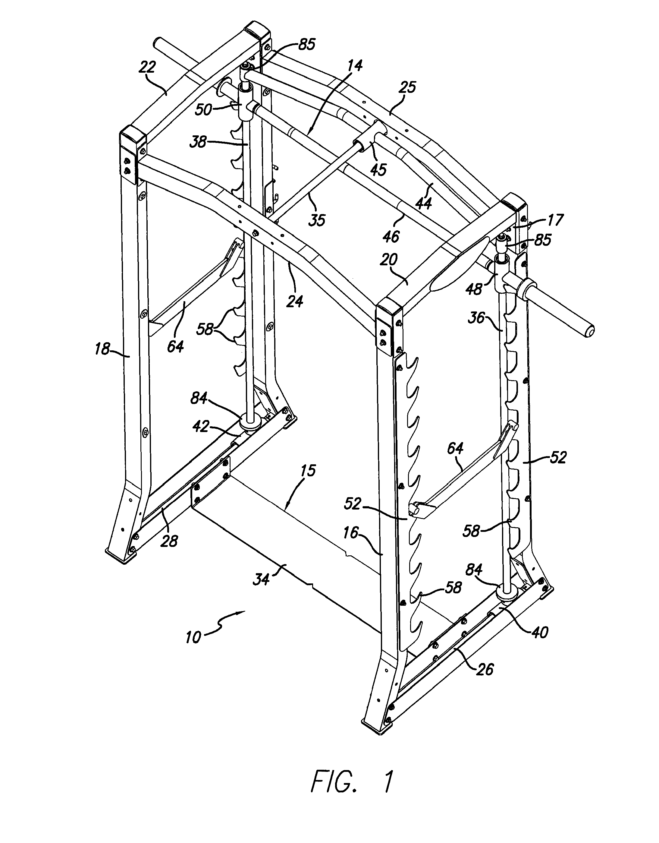
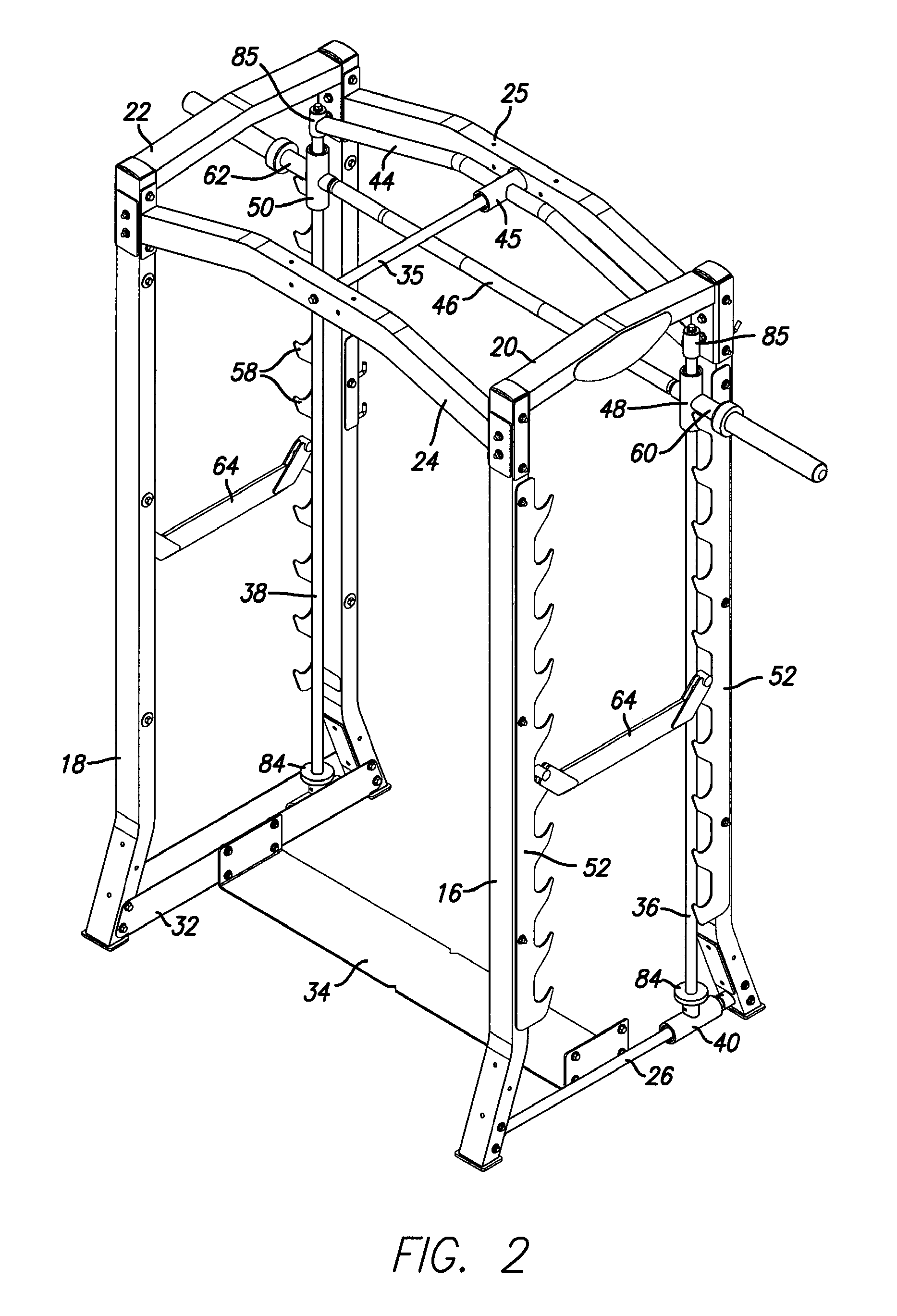
[0054] FIGS. 1 to 10 illustrate a dual action weightlifting exercise machine10 according to the present invention. The apparatus basically comprises a stationary main frame 12 and an exercise unit 14 movably mounted on the stationary frame. The movable exercise unit 14 is shown separately in FIG. 9, with most of the stationary frame parts removed for clarity.

[0055] The stationary frame 12 is designed to support the movable exercise unit and comprises a floor engaging base 15, first and second pairs of upright struts 16, 17 and 18, 19, respectively, upper struts 20, 22 extending between the upper ends of each pair of upright struts, and upper cross struts 24, 25, the first upper cross strut 24 extending between the upper ends of the front upright strut 16, 18 of each pair, and the second upper cross strut 25 extending between the upper ends of the second upright strut 17, 19 of each pair. A pair of lower horizontal guide bars 26, 28 extends between the lower ends of each pair of cros...

second embodiment

[0069] FIGS. 15 to 21 illustrate a dual action weightlifting exercise machine 100 according to the invention. In this embodiment, there are two upper horizontal guides and two upper horizontal slides attached to the traveling cross bar which extends between the upper ends of the vertical guides. There are also two lower horizontal guides and associated horizontal slides. Unlike the previous embodiment, the respective lower horizontal slides are connected to the vertical guides in an offset manner rather than being positioned directly under the lower ends of the vertical guides, as in FIGS. 1 to 11. Other parts of the machine 100 are identical to those of FIGS. 1 to 11, and like reference numerals have been used for like parts as appropriate.

[0070] The machine 100 basically comprises a stationary main frame and a movable exercise unit which is movably mounted on the frame. As in the first embodiment, the main frame has a floor engaging base 15, first and second pairs of upright strut...


PUM


Abstract

A dual action weightlifting machine has a stationary frame and first and second spaced vertical guides slidably mounted on the stationary frame for horizontal sliding movement relative to the frame. A horizontally extending exercise bar assembly has spaced first and second vertical slides slidably mounted on the vertical guides for vertical sliding movement relative to the frame, a user engaging portion for gripping by a user when performing weightlifting exercises, and opposite end portions for receiving one or more selected weights. The user engaging portion is located between the vertical slides and rotatably mounted relative to the vertical slides for free rotation through 360 degrees, so that the user's hands may be rotated relative to the vertical slides while lifting weights.

Description

RELATED APPLICATION [0001] The present application is a Divisional of co-pending U.S. patent application Ser. No. 11 / 363,677 filed on Feb. 18, 2006, which is also incorporated herein by reference in its entirety.BACKGROUND [0002] 1. Field of the Invention [0003] The present invention relates generally to weightlifting exercise machines, and is particularly concerned with exercise machines of the type which have a guided exercise bar or weight bar to simulate free weight barbell exercise movements. [0004] 2. Related Art [0005] Weightlifting machines with weight bars for simulating barbells, also known as Smith machines, have been a fitness club staple for many years. The basic machine has a barbell attached to slide mechanisms which run on vertical guides on opposite sides of a stationary frame. This allows an exerciser to perform exercises with vertical up and down movement, such as squats, bench press exercises, and the like, but does not permit any horizontal movement. The exercis...

Claims


Application Information

Patent Timeline
Patent Type & Authority Applications(United States)
IPC IPC(8): A63B21/062
CPCA63B21/0613A63B2021/0783A63B2021/0614A63B21/078A63B21/0624A63B21/0626A63B21/0783
Inventor WEBBER, RANDALL T.
Owner HOIST FITNESS SYST
Learn More