
Low Friction Live-Loaded Packing

a technology of live-loaded packing and valve stem, which is applied in the direction of spindle sealing, transportation and packaging, valve operating means/releasing devices, etc., can solve the problems of reducing the amount of rotation that can occur in the valve stem, increasing the cost of the bellows seal, and limiting the rotational amount of the valve stem, so as to reduce the friction of packing and packing wear, reduce the effect of packing friction and packing wear

Active Publication Date: 2008-02-28
FISHER CONTROLS INT LLC
View PDF25 Cites 26 Cited by
  • Summary
  • Abstract
  • Description
  • Claims
  • Application Information

AI Technical Summary

Benefits of technology

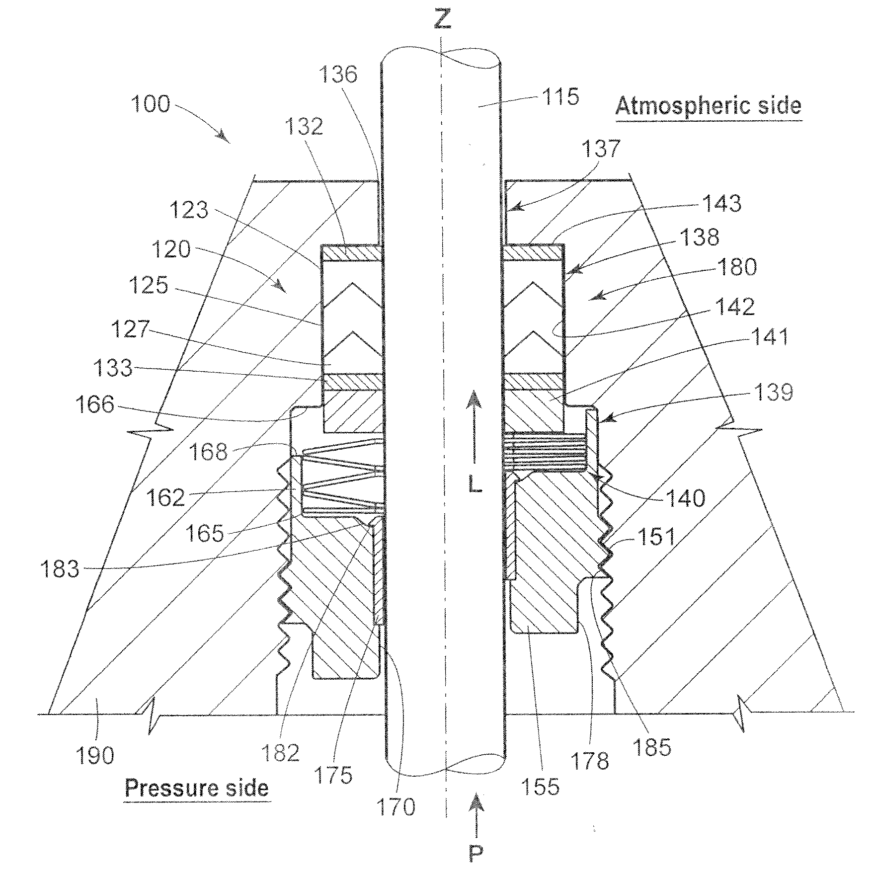
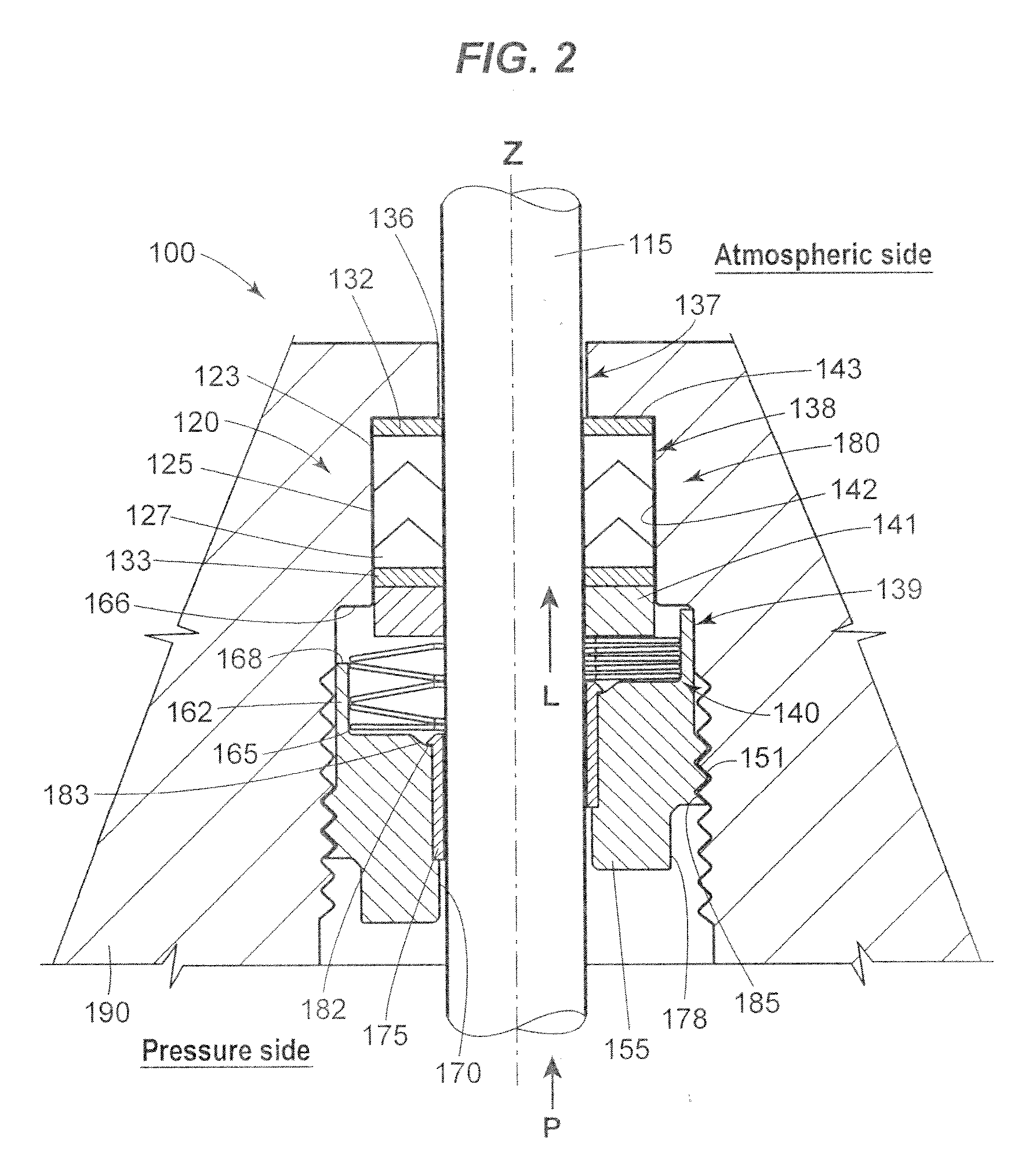
[0012] In an example packing assembly, a seal assembly comprising a seal component to provide a fluid seal around a valve stem and an anti-extrusion component to substantially prevent extrusion of the seal component about the valve stem and a loading assembly to provide a predetermined packing stress upon the seal assembly to couple the packing stress between the loading means and the seal assembly. The packing assembly further includes a packing retainer adapted to receive at least one of the seal assembly and loading assembly and is configured to couple the seal assembly and loading assembly to the control valve assembly. The packing retainer further includes a shoulder to engage a packing box within the control valve assembly to control a loading assembly preload to provide a predetermined packing stress to substantially reduce the packing friction and packing wear in the control valve assembly.
[0013] In another example packing assembly, a cartridge packing assembly comprises a seal assembly having a seal component to provide a fluid seal around the valve stem and, at least, a first anti-extrusion component to substantially prevent extrusion of the seal member about the valve stem and a loading assembly having a loading means to provide a predetermined packing stress upon the seal assembly and a follower component to couple the loading means to the seal assembly. The packing assembly further comprises a packing retainer adapted to be disposed in a packing box of the control valve assembly to receive the seal assembly and the loading assembly and having a shoulder to engage the control valve assembly to control the preload of the loading assembly to provide a predetermined packing stress to substantially reduce the packing friction and packing wear in the control valve assembly. The example packing retainer further includes an adjustment means to modify the packing stress upon installation.

Problems solved by technology

Both special metals significantly increase the cost of the bellows seal.
Additionally, bellows seals are expensive to install as the bellows are generally seal-welded to the valve stem, gasket-sealed at the bonnet / valve joint and require an extended valve bonnet.
The physical construction of the bellows and this installation method also places limits on the amount of rotation that can occur in the valve stem.
Applications producing travel greater than the designed length of travel may damage the bellows by extending the “folds” beyond the designed length causing premature cycle fatigue or cracking to occur.
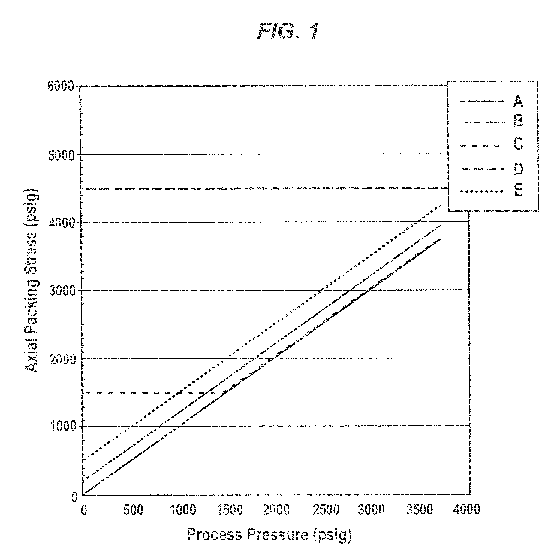
One skilled of ordinary skill in the art should appreciate that packing stresses below the process pressure, A, may generally result in process fluid leaks since the process pressure may overwhelm a seal formed by the packing stress.
This type of packing is typically rated for environmental service at a maximum pressure of 750 psi and a maximum temperature of 450° F. One issue with this type of packing assembly relates to the uses of Belleville springs to load the packing.
Although the Belleville springs provide the required packing stress, the travel or range of compression of the Belleville springs is quite low.
As such, normal manufacturing tolerances within the control valve assembly necessitate manual adjustment, which can be very difficult and time consuming (e.g., the Fisher Controls Design D2 dump valves uses three Belleville spring stacked in series, which require adjustment precision within ±0.0024 inches to achieve a packing stress within ±50 psi).
Thus, if the packing stress is too high, high packing friction may result, which can reduce control valve performance and packing life.
Additionally, coil springs typically are not used with high pressure, double V-ring packing due to the fact that bonnet / packing box area is limited and the cross-sectional area of coil spring needed to develop the proper spring rate will be too large Furthermore, this type of packing set is typically loaded from the outboard side (i.e. external or atmospheric side as compared to the inboard or pressure side) of the control valve providing a packing force that opposes a force produced by the process pressure.
This overcompensation in the initial packing stress creates greater friction in the assembly, which may cause the control valve actuator to be oversized, thereby adding expense to the control valve and resulting in greater packing wear during operation.
Although this type of packing is rated for environmental service at a maximum pressure of 1500 psi and a maximum temperature of 600° F., the friction levels produced by this packing arrangement may be substantially higher than PTFE packing at temperatures below 300° F. and may be unacceptable in certain types of applications (e.g., applications without control valve positioners).

Method used


Image

  • Low Friction Live-Loaded Packing
  • Low Friction Live-Loaded Packing
  • Low Friction Live-Loaded Packing

Examples


Embodiment Construction

[0019] The example packing assembly uses a stack of seal rings and anti-extrusion rings to provide a high-pressure fluid seal assembly around a control valve shaft. The seal assembly may be characterized as follows: 1) a loading assembly, such as a Belleville spring stack, that provides compliant packing stress with sufficient travel to provide improved adjustments in packing wherein the packing stress is exerted in the same direction as a fluid pressure exerted by the process fluid; 2) a packing retainer arranged to engage a control valve body or bonnet assembly to substantially eliminate the need to initially adjust the packing stress to overcome or offset the process pressure thereby providing an environmental seal with reduced friction and reduced packing set wear; 3) a seal assembly with anti-extrusion washers and rings that substantially reduces valve shaft and / or seal wear during operation; and 4) a cartridge seal assembly that substantially improves the repair or replacement...


PUM


Abstract

A valve packing assembly for a control valve includes a seal assembly, a loading assembly, and a packing retainer. The seal assembly has a seal component to provide a fluid seal around a valve stem and an anti-extrusion component to substantially prevent extrusion of the seal component about the valve stem. The loading assembly is configured to advantageously provide a predetermined packing stress to the seal assembly that is in the same direction as a process stress applied to the seal assembly by a process fluid, thereby substantially reducing packing friction and packing wear in the control valve assembly.

Description

CROSS-REFERENCE TO RELATED APPLICATIONS [0001] This application claims the benefit of priority of U.S. Provisional Patent Application No. 60 / 840,369, filed Aug. 25, 2006, the entire contents of which are hereby expressly incorporated herein by refernce.FIELD OF THE INVENTION [0002] disclosure relates generally to packing for valves, and more particularly, to an improvement of live-loaded packing for control valves used in process control applications that require very low emission levels from valve packing. BACKGROUND OF THE INVENTION [0003] In the process control industry, it is known that many process applications require control valves that leak very small amounts of a process fluid into the surrounding environment. In fact, some process plants are subject to federal regulation under the 1990 Amendments to the Clean Air Act which regulates the amount of certain process emissions, such as aromatic or chlorinated hydrocarbons, based upon measured emission concentrations (e.g., less...

Claims


Application Information

Patent Timeline
IPC IPC(8): F16K1/02F16K31/44
CPCF16K41/02Y10T137/6021Y10T137/6069
Inventor LOVELL, MICHEL KENGRABAU, TED DENNIS
Owner FISHER CONTROLS INT LLC
Learn More