
Transmission using multiple physical interface

Active Publication Date: 2008-02-21
AVAGO TECH INT SALES PTE LTD
View PDF12 Cites 86 Cited by
  • Summary
  • Abstract
  • Description
  • Claims
  • Application Information

AI Technical Summary

Benefits of technology

[0009]A System On Chip (SOC) unit enabled to transmit data via one or more physical interfaces is provided. The SOC comprises a processor and a network interface including multiple physical input/output (I/O) interfaces coupled to the processor. In response to r

Problems solved by technology

However, for communication between devices that have multiple I / O interfaces and are not required to follow a PCI topology, inter-device data transfer latency is often long.
Furthermore, a device having multiple I / O interfaces cannot take full advantage of the I / O bandwidth when following a PCI model for all transmissions.

Method used


Image

  • Transmission using multiple physical interface
  • Transmission using multiple physical interface
  • Transmission using multiple physical interface

Examples


example pci topology

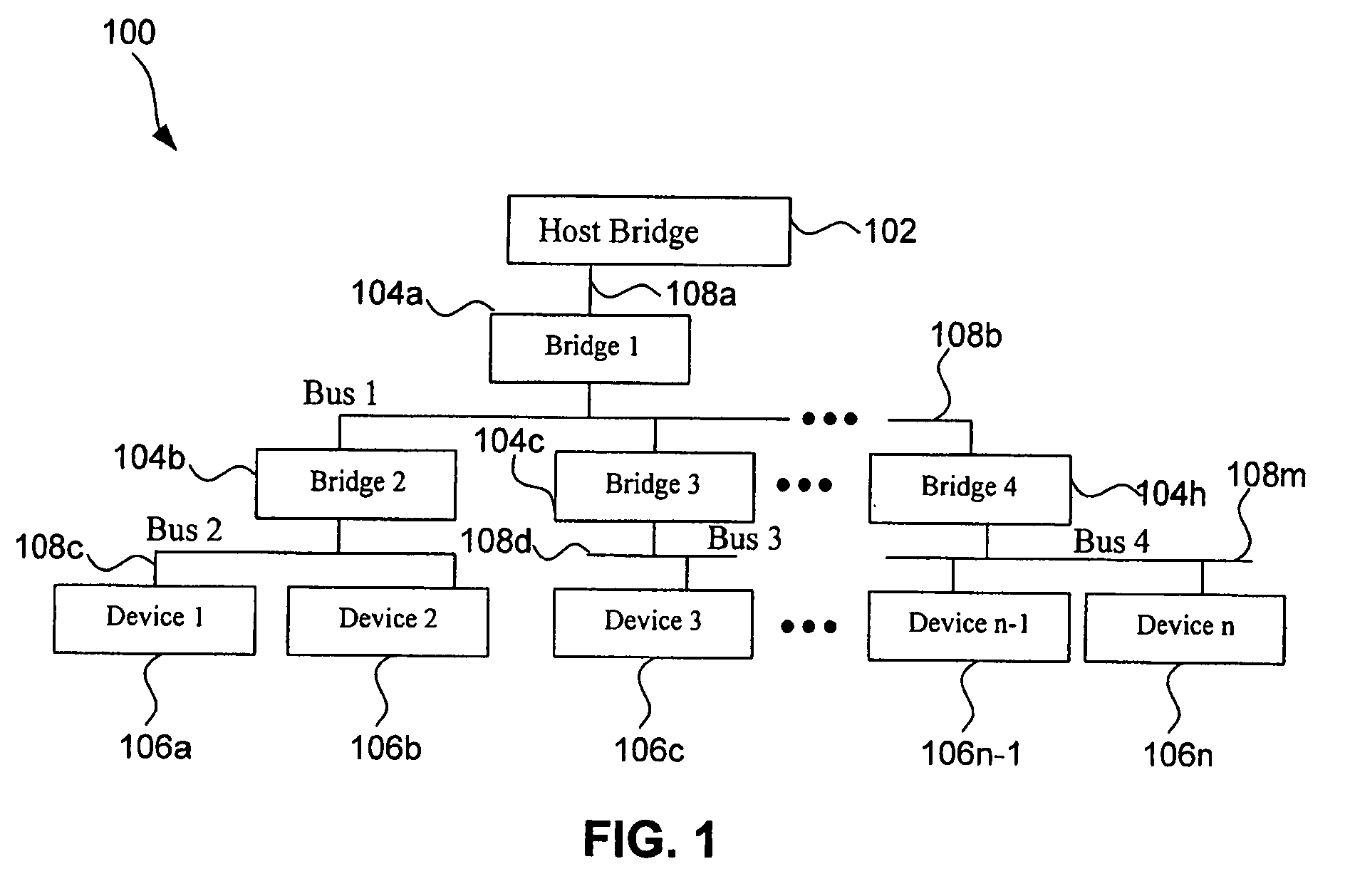
[0028]FIG. 1 illustrates system 100 in a PCI tree topology. System 100 comprises a host bridge 102, bridges 104a-h and devices 106a-n connected by buses 108a-m. Host bridge 102, bridges 104a-h and devices 106a-n may be one or more of network cards, network processors and System on Chips (SOC). Host bridge 102 defines the root of system 100. Bridges 104a-h form a hierarchical network connected by buses 108a-m. Each bridge 104 is associated with a range of device addresses and is enabled to route data to a device 106 that has an address in that range of addresses. Devices 106a-n form “leaves” of the hierarchical bus network.

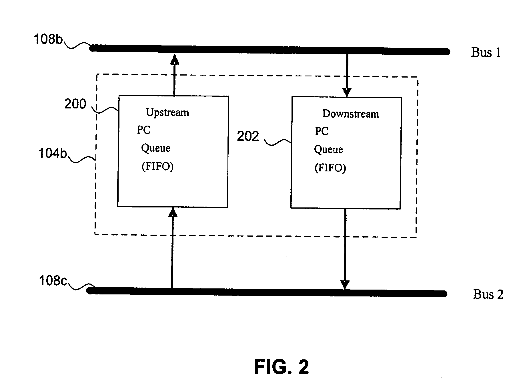
[0029]If the underlying transmission protocol in system 100 is, for example, a PCI protocol or another protocol that requires strictly ordered transmission, then there is a long latency for communication between devices 104. For example, as shown in FIG. 1, for device 106a to send data to device 106n-1 using a PCI model, data is pushed up to bridge 104b followed by...

example embodiments

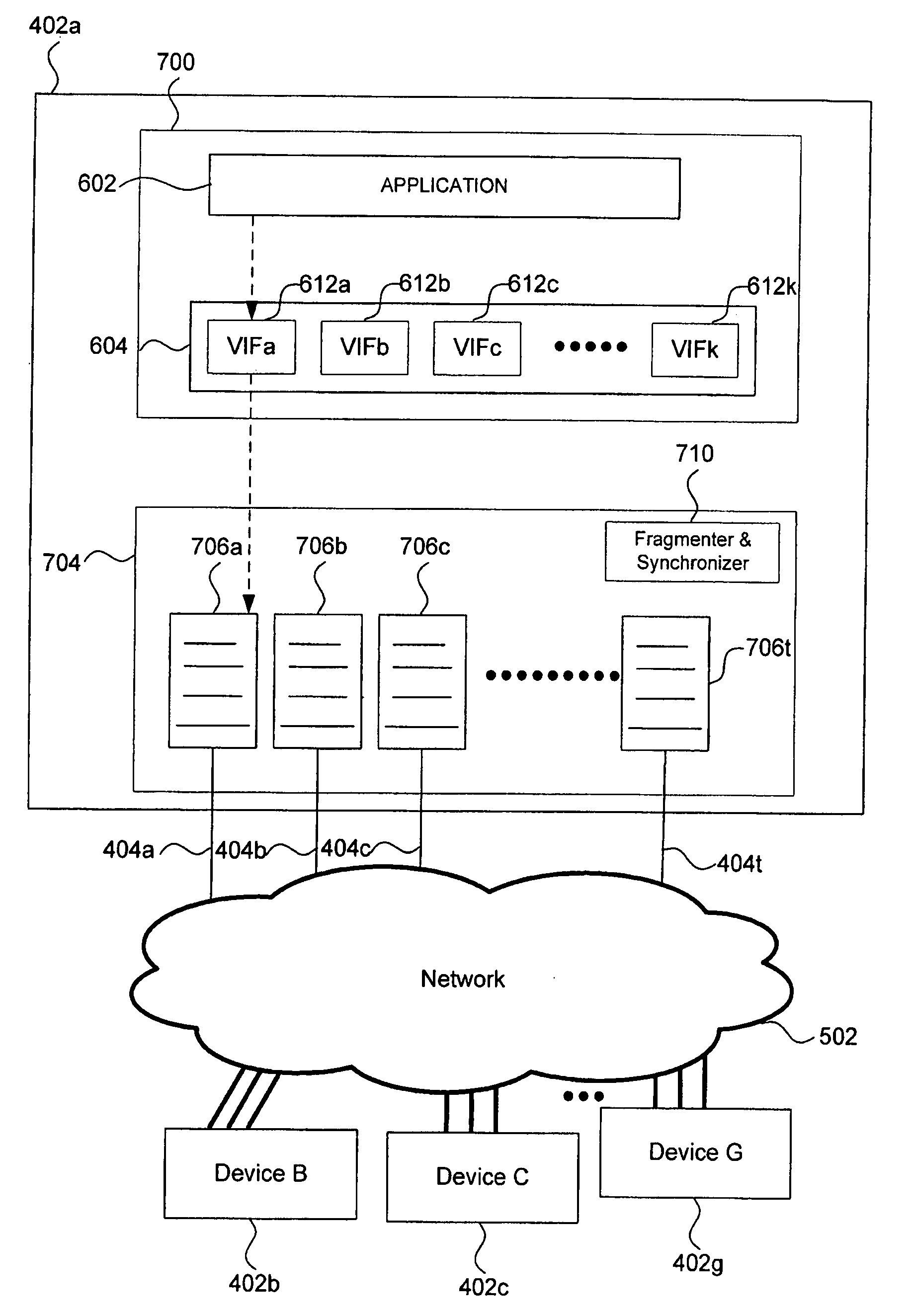
[0035]FIG. 5 illustrates an example system 500 comprising devices 402a-g having multiple I / O interfaces 404a-t according to an embodiment of the invention. Devices 402 are connected via packet-switching network 502. If communication between devices 402 does not algorithmically require use of a strictly ordered topology, for example a PCI topology, data packets can be routed in random order through more than one of the multiple I / O interfaces of devices 402. In system 500 devices 402 are peers. When a PCI topology or similar “producer-consumer” topology is required, tree topology 504 is pre-configured such that device 402a functions as a root and devices 402b-g function as intermediate bridges or leaves.

[0036]FIG. 6 illustrates an exemplary communication stack 600 according to an embodiment of the invention. Communication stack 600 comprises five layers 602-610 with application layer 602 being the top layer. Application layer 602 sends and receives data to / from shim layer 604. Shim l...


PUM


Abstract

A method to transmit data using a device having a plurality of physical input / output (I / O) interfaces is provided. The method comprises receiving data and determining a topology according to which data is to be transmitted. Data is transmitted in sequential order via a single physical interface for a first topology and in random order via a plurality of physical interfaces for a second topology.A System On Chip (SOC) unit enabled to transmit data via one or more physical interfaces is provided. The SOC comprises a processor and a network interface including multiple physical input / output (I / O) interfaces coupled to the processor. In response to receiving data for transmission, the processor is enabled to select a single I / O interface for sequential data transmission according to a first topology or select multiple physical I / O interfaces for random order data transmission according to a second topology.

Description

CROSS-REFERENCE TO RELATED APPLICATIONS[0001]This application claims the benefit of U.S. Provisional Application No. 60 / 837,639 filed Aug. 15, 2006, which is incorporated herein by reference in its entirety.BACKGROUND OF THE INVENTION[0002]1. Field of the Invention[0003]The present invention generally relates to communications systems.[0004]2. Background Art[0005]Multiple devices can be configured in Peripheral Component Interconnect (PCI) input / output (I / O) tree topology. A host bridge often defines the PCI root of a hierarchical PCI tree topology. However, for communication between devices that have multiple I / O interfaces and are not required to follow a PCI topology, inter-device data transfer latency is often long. This is because data is transmitted sequentially via a single I / O interface. Furthermore, a device having multiple I / O interfaces cannot take full advantage of the I / O bandwidth when following a PCI model for all transmissions.[0006]Methods and systems are needed to ...

Claims


Application Information

Patent Timeline
IPC IPC(8): H04L12/56
CPCG06F13/4022H04L49/70H04L49/109
Inventor PONG, FONGNING, CHUN
Owner AVAGO TECH INT SALES PTE LTD
Learn More