
Storage apparatus, control method, control device, and program

a technology for storage apparatus and control methods, applied in data recording, instruments, magnetic recording, etc., can solve the problems of not being able to perform, the height of the flying apparatus the flight height cannot be set lower than the common range, so as to reduce the variation of the reproduced amplitude, accurately determine the effect of the measuremen

Inactive Publication Date: 2008-02-21
KK TOSHIBA
View PDF4 Cites 15 Cited by
  • Summary
  • Abstract
  • Description
  • Claims
  • Application Information

AI Technical Summary

Benefits of technology

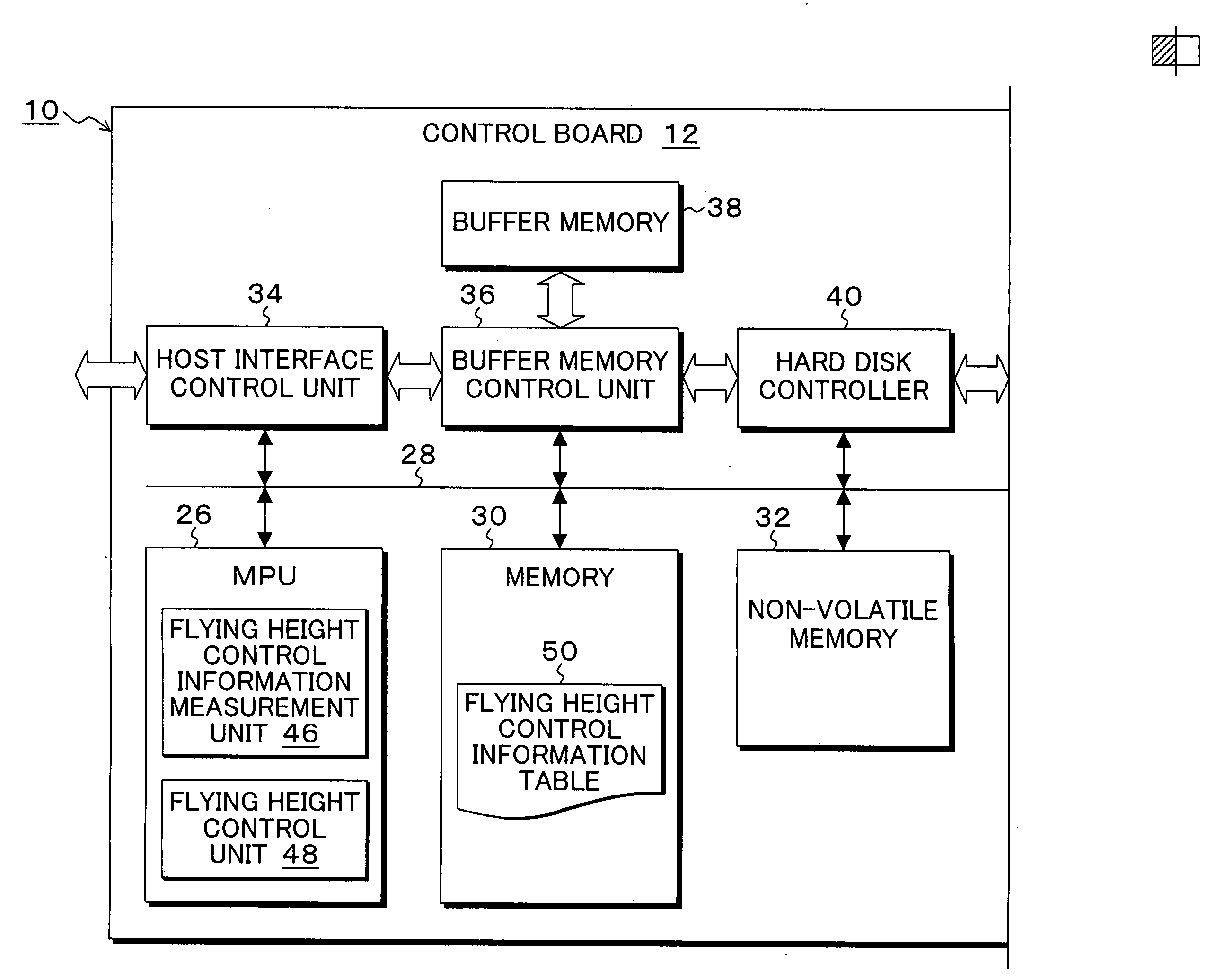
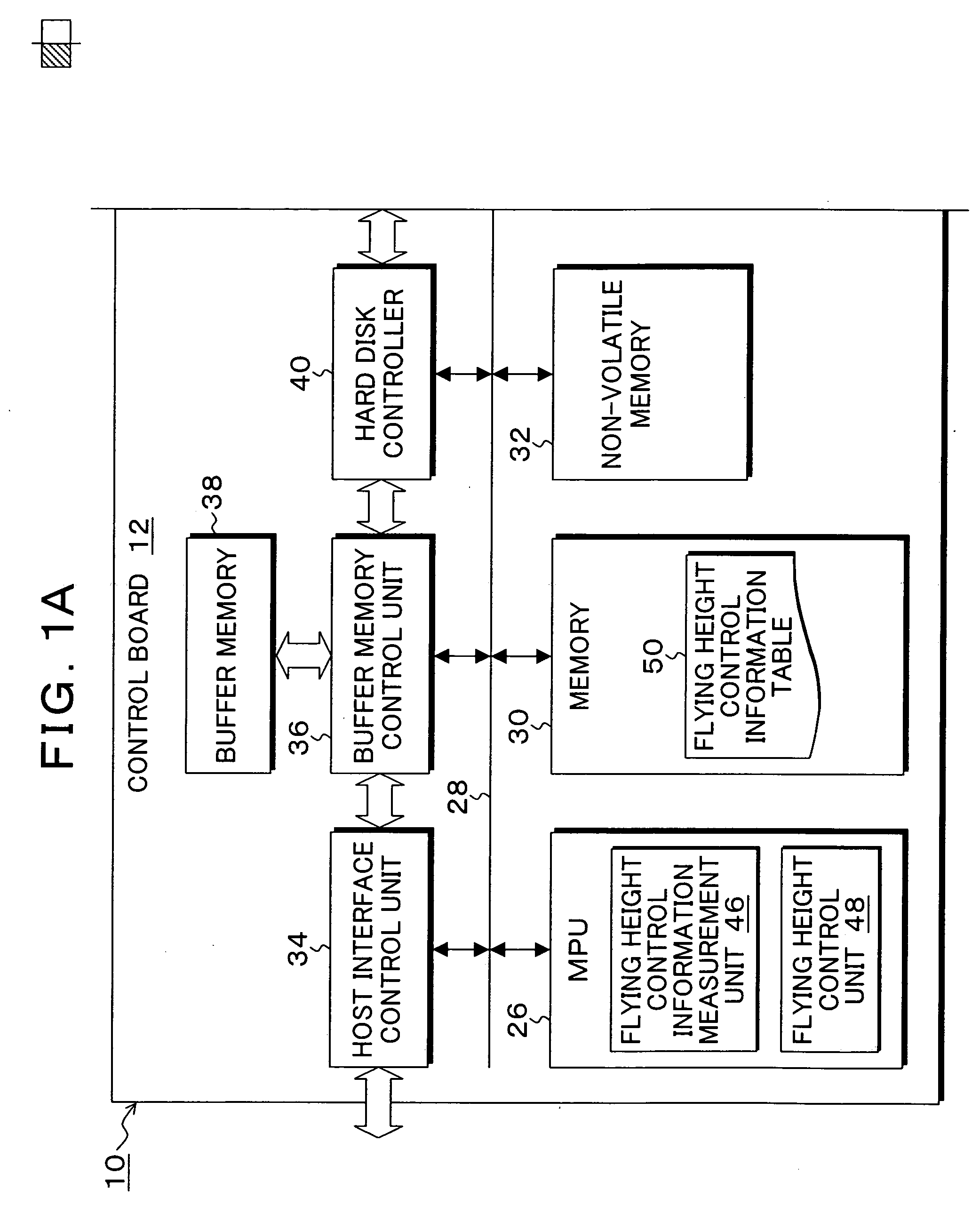
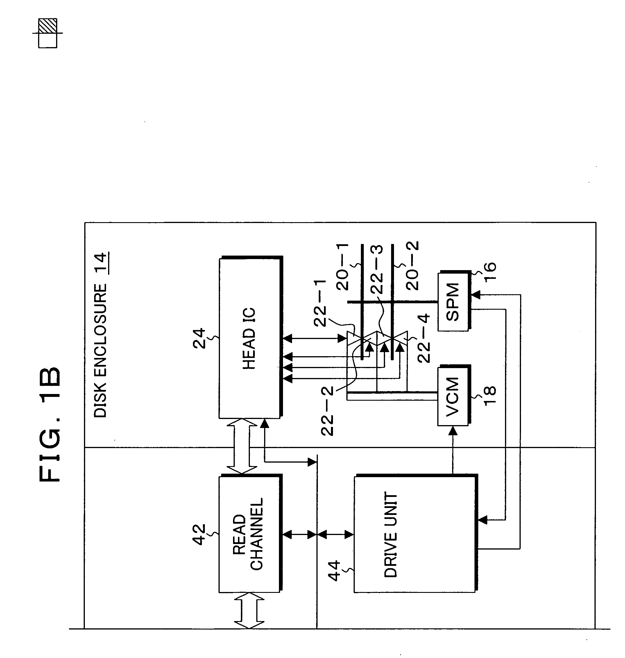
[0007]According to the present invention to provide a storage apparatus, a control method, and a program which can perform highly accurate control so that the flying height of a head with respect to a medium recording surface can be accurately measured by controlling the electric power amount distributed to a heater provided in the head.

Problems solved by technology

However, when the flying height of the head is reduced, collision with minute protrusions on the magnetic disk surface is readily generated, and variation of the clearances between heads is present in the range of mechanical common differences; therefore, there is a problem that the flying height cannot be set lower than the range of common differences when the medium contact is taken into consideration.
However, in such conventional methods of controlling the flying height between the head and the magnetic disk recording surface, basically, the protrusion value is adjusted so that reproduction can be performed without causing medium contact by utilizing the fact that flying height is changed due to expansion / protrusion of the head flying surface when the heater is heated by distributing electric power; and there has been a problem that highly precise flying height control of controlling the flying height upon recording and reproduction to a constant target flying height by taking variation of the flying heights which are different in each head into consideration cannot be performed.
However, in recent magnetic disk apparatuses, contact-start-stop of the head is abolished, and a head retained in a ramp load mechanism is delivered to the disk surface upon activation of the apparatus in the state in which the magnetic disk is rotating, thereby causing it to fly from the beginning; thus, there is a problem that the amplitude change while the head which is in contact with the magnetic disk surface is flying cannot be detected, and the flying height cannot be measured from unchanged amplitude of the reproduction signal of the head which is flying with a constant flying height.

Method used


Image

  • Storage apparatus, control method, control device, and program
  • Storage apparatus, control method, control device, and program
  • Storage apparatus, control method, control device, and program

Examples


first embodiment

[0111]FIG. 12 is a graph diagram of measurement results showing the relation of the mean amplitude and the contact determination value with respect to the heater electric power in the first embodiment shown in the flow chart of FIGS. 10A and 10B. In FIG. 12, a measurement curve 152 represents the mean amplitude μ, and a measurement curve 162 represents the contact determination value S1. In this case, the cycle number n of the measurement curves 152 and 162 is n=50. For the measurement curve 162 of the contact determination value S1, a threshold value Sth for determining the contact with the magnetic disk is set as Sth=0. Therefore, when a measurement point 163 at which the measurement characteristic 162 of the contact determination value S1 is equal to or less than the threshold value Sth=0 along with increase of the heater electric power P, it is determined that the head is in contact with the magnetic disk, and the flying height do is calculated by multiplying the heater electric...

second embodiment

[0113]FIG. 14 shows a calculation principle of a contact determination value S2(i) in the flying height measurement process. FIG. 14 shows the mean amplitude μ obtained from the measurement amplitude of the preamble read signal with respect to the heater electric power P of the horizontal axis and shows measurement points by circles. When a current measurement point to which attention is focused on for the calculation process herein is 164, a next measurement point is 166, a previous measurement point is 168, and a measurement point before the previous one is 170, the heater electric power at the measurement points 164, 166, 168, and 170 are disposed along with the time course as P(i−2), P(i−1), P(i), P(i+1).

The mean amplitude is disposed along with the time course as

[0114]μ(i−2), μ(i−1), μ(i), μ(i+1).

In the second embodiment, with respect to such four successive measurement points 164, 166, 168, and 170, the measurement point 164 to which attention is focused on for calculation is ...

third embodiment

[0128]FIG. 22 is a graph diagram showing the relation between the standard deviation σ in FIGS. 20A and 20B and the frame number m for measuring preamble read signals per one rotation to obtain the mean amplitude. In FIG. 22, a measurement curve 208 is that of the case in which the heater electric power P=0 mW, in other words, there is no heater electric distribution, and the mean amplitude μ is generally stabilized to be constant relative to increase in the cycle number n after exceeding the cycle number n=10. A measurement curve 20 is that of the case in which the heater electric power P=39 mW, and, also in this case, it is generally stabilized to be constant after exceeding the frequency number n. Furthermore, a measurement curve 212 is that of the case of contact start in which the heater electric power P=69 so as to further reduce the heater flying height. The mean amplitude μ is increased overall along with reduction in the flying height; however, it is generally stabilized af...


PUM

PropertyMeasurementUnit
temperatureaaaaaaaaaa
electric poweraaaaaaaaaa
temperatureaaaaaaaaaa

Abstract

An amplitude measurement unit measures an amplitude of a read signal from a preamble unit in a servo area of a predetermined frame number m per one rotation of the recording medium for a predetermined cycle number n while increasing an electric power amount distributed to the heater in the state in which the head is positioned to a track on the recording medium, and a mean amplitude calculating unit calculates a mean amplitude from an amplitude measurement value which is measured by the number which is the frame number m multiplied by the cycle number n. A contact determination unit calculates a mean amplitude variation amount per a unit heater electric power amount as a contact determination value, and determines that the head is in contact with the recording medium when the contact determination value is lower than a predetermined threshold value, and a flying height calculating unit which calculates a flying height of the head with respect to the surface of the recording medium from the heater electric power amount at the point when contact is determined.

Description

[0001]This application is a priority based on prior application No. 2006-222967, filed Aug. 18, 2006, in Japan.BACKGROUND OF THE INVENTION[0002]1. Field of the Invention[0003]The present invention relates to a storage apparatus, a control method, a control device, and a program for reading / writing data by flying a head above a rotating recording medium, and particularly relates to a storage apparatus, a control method, a control device, and a program for controlling a flying height between a head and a recording medium to a predetermined target flying height by changing a protrusion value by thermal expansion which accompanies electric power distribution to and heating of a heater provided in the head.[0004]2. Description of the Related Arts[0005]Conventionally, the flying height of the head with respect to the recording surface of a magnetic disk has to be reduced in order to realize a high recording density of a magnetic disk apparatus, and a flying height of 10 nm order is realiz...

Claims


Application Information

Patent Timeline
Patent Type & Authority Applications(United States)
IPC IPC(8): G11B21/02G11B27/36
CPCG11B5/6005G11B5/607
Inventor YAMASHITA, SATOSHISAITOU, SYUNJIABE, YUKIOYANAGI, SHIGENORI
Owner KK TOSHIBA
Learn More