
Valve unit, reaction apparatus with the same, and method of forming valve in channel

a valve unit and reaction apparatus technology, applied in the direction of soldering apparatus, manufacturing tools, laboratory glassware, etc., can solve the problems of difficult to accurately control the time at which the channel is opened, the process of paraffin wax takes a lot of heating time, and the difficulty of miniaturizing and integrating a substrate for a biochemical reaction

Active Publication Date: 2008-02-21
PRECISIONBIOSENSOR INC
View PDF7 Cites 16 Cited by
  • Summary
  • Abstract
  • Description
  • Claims
  • Application Information

AI Technical Summary

Problems solved by technology

However, a large amount of paraffin wax is needed to close the minute channel, and a large sized heating member is needed to melt the large amount of paraffin wax, which make it difficult to miniaturize and integrate a substrate for a biochemical reaction.
Also, the melting process of the paraffin wax takes a lot of heating time and it is difficult to accurately control a point of time at which the channel is opened.

Method used


Image

  • Valve unit,  reaction apparatus with the same, and method of forming valve in channel
  • Valve unit,  reaction apparatus with the same, and method of forming valve in channel
  • Valve unit,  reaction apparatus with the same, and method of forming valve in channel

Examples


Embodiment Construction

[0046]Hereinafter, the present invention will now be described in detail with reference to the accompanying drawings.

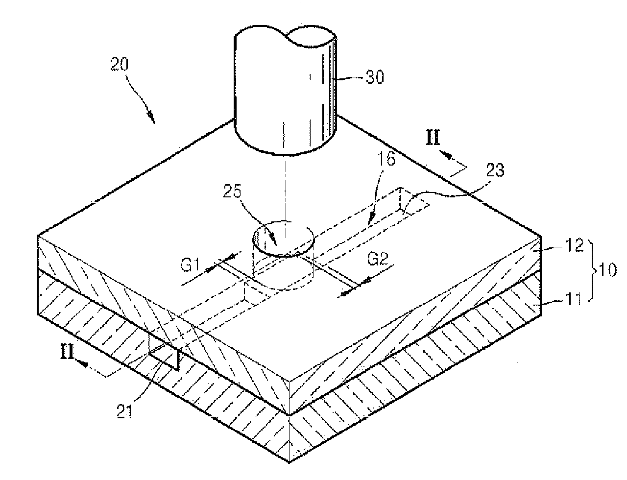
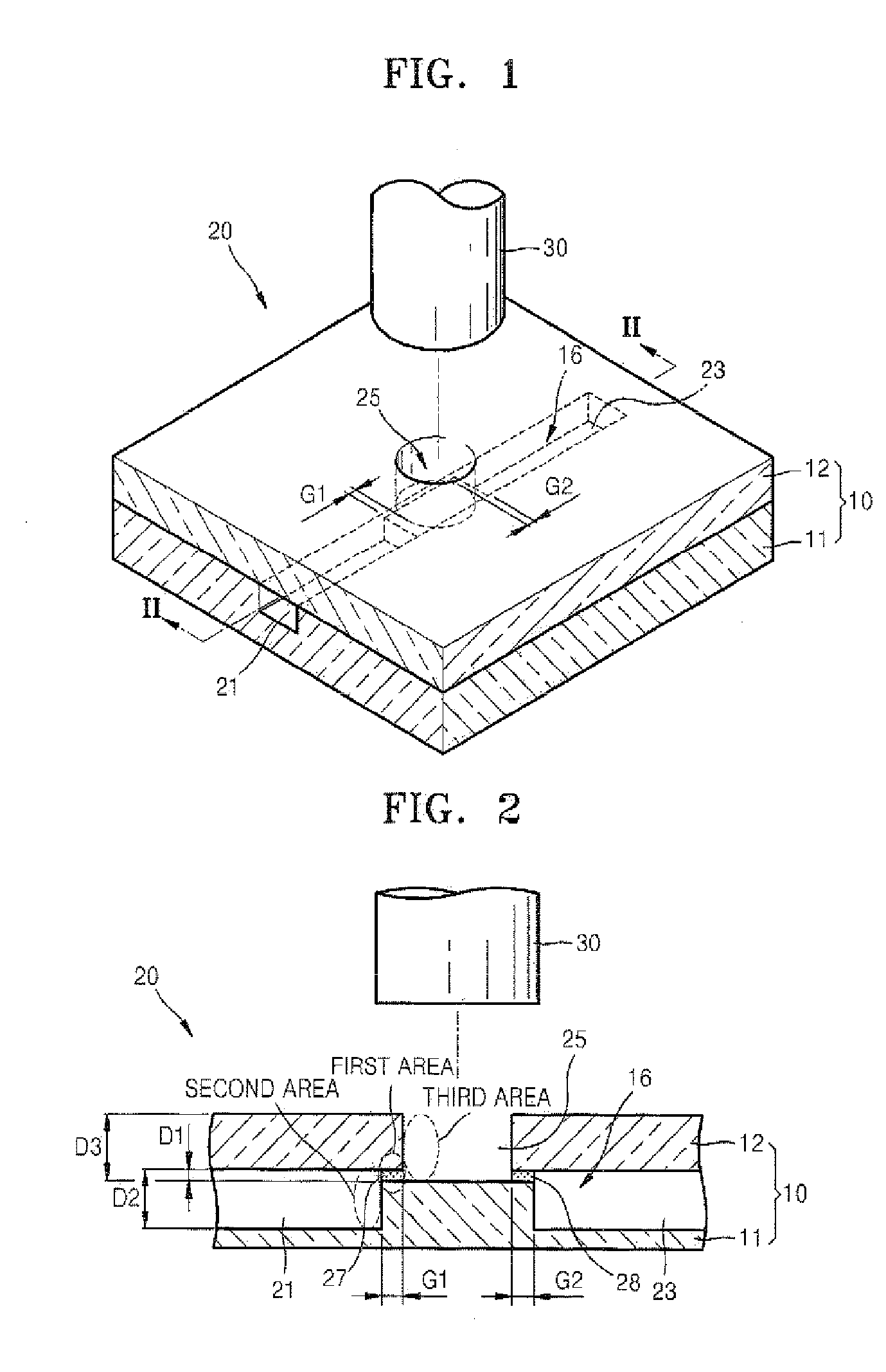
[0047]FIG. 1 is a perspective view of a valve unit according to an embodiment of the present invention, and FIG. 2 is a cross-sectional view of the valve unit taken along line II-II of FIG. 1.

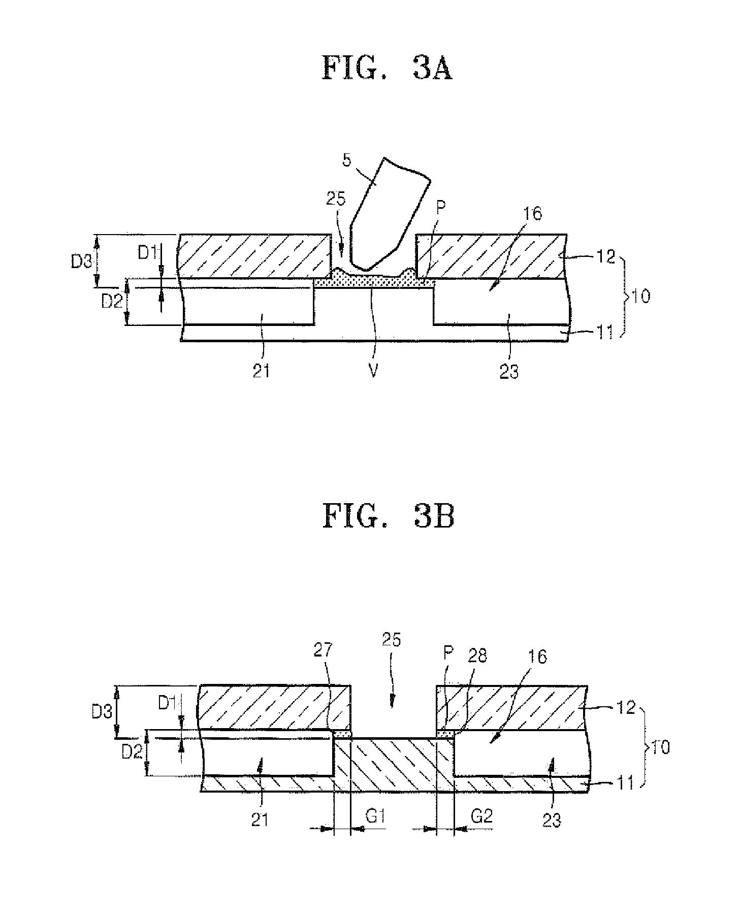
[0048]Referring to FIGS. 1 and 2, a valve unit 20 according to an exemplary embodiment of the present invention includes a fluid channel 16 constituting a flow path of a fluid and having a portion containing a first area of a first dimension (“D1”), a second area of a second dimension (“D2”), and a third area of a third dimension (“D3”), and a valve 27, 28 formed in the first area of the fluid channel 16 by filling the first area. The valve 27, 28 is made of a phase changeable valve material, which may include a heat generating particles. The dimensions D1 is smaller than D2 and D3. The first area is sided by the second area and the third area on each side, and the first area has...


PUM

PropertyMeasurementUnit
energyaaaaaaaaaa
wavelengthaaaaaaaaaa
distanceaaaaaaaaaa

Abstract

A valve unit, a reaction apparatus with the same, and a method of forming a valve by injecting a valve material into a channel are provided. The valve unit comprises a fluid channel constituting a flow path of a fluid and having a portion containing a first area of a first dimension (“D1”) and a second area of a second dimension (“D2”), wherein D1<D2, the second area is located on one side of the first area, and the first area has a distance of G in the direction of the fluid channel; and a valve formed in the first area of the fluid channel by filling the first area and made of a phase changeable valve material.

Description

CROSS-REFERENCE TO RELATED PATENT APPLICATIONS[0001]This application claims priority from Korean Patent Application Nos. 10-2006-0077127, filed on Aug. 16, 2006 and 10-2006-0092926, filed on Sep. 25, 2006 in the Korean Intellectual Property Office, the disclosures of which are incorporated herein in their entirety by reference.BACKGROUND OF THE INVENTION[0002]1. Field of the Invention[0003]Apparatuses and methods consistent with the present invention relate to a valve unit for closing a flow path of a fluid and timely opening the flow path such that the fluid flows along a channel, a reaction apparatus with the same, and a method of forming a valve for opening and closing a flow path of a fluid in a channel.[0004]2. Description of the Related Art[0005]A minute channel constituting a flow path for a fluid is formed in a substrate (i.e., a lab-on-a-chip) used for a biochemical reaction, for example, a lysis reaction or polymerase chain reaction (PCR). A valve unit that closes the minu...

Claims


Application Information

Patent Timeline
Patent Type & Authority Applications(United States)
IPC IPC(8): F16K51/00
CPCB01L3/502738B01L2300/0806B01L2300/087B01L2300/0887B01L2300/1861Y10T29/49405F16K99/0001F16K99/0032F16K99/004F16K2099/0084B01L2400/0677Y10T137/2196
Inventor PARK, JONG-MYEONLEE, JEONG-GUN
Owner PRECISIONBIOSENSOR INC
Learn More