
Magnetic device for holding and driving bits and fasteners

a magnetic device and drive technology, applied in the field of tools and tool bits, can solve the problems of high cost, cumbersome use, and inability to capture a major fraction of the magnetization force of the typical tool configuration, and achieve the effects of easy insertion or removal, variable magnetic strength, and increased magnetic field

Active Publication Date: 2008-02-21
COMBINED PRODS
View PDF10 Cites 1 Cited by
  • Summary
  • Abstract
  • Description
  • Claims
  • Application Information

AI Technical Summary

Benefits of technology

[0007] Another object of the present invention is to provide a compact magnetic bit holder that can be used as a fastener driver. A feature of the present invention is a magnetized annulus defining an aperture which is adapted to slidably receive a tool bit, a tool shank, or a fastener so as to impart magnetic and mechanical force thereto. An advantage of the present invention is that it allows the direct application of magnetic force to a bit or fastener with or without the application of mechanical force to the bit or fastener. A further advantage of the present invention is that the magnetic ring may be used as a removable handle for a bit or fastener.
[0008] Still another object of the present invention is to provide a magnetic bit, fastener, or nut holder with variable magnetic strength A feature of the present invention is that magnetic rings can be stacked coaxially. An advantage of the present invention is that the available magnetic field can be increased as needed. Another advantage is that coaxial stacking enlarges the exterior-facing surface of the handle to which a mechanical torque-imparting tool (such as a wrench) can be applied.
[0009] Yet another object of the present invention is to provide a magnetic bit, fastener, or nut holding device that allows for quick interchange of tool bits, fasteners, or nuts. A feature of the present invention is that the device is adapted to slidably receive tool shanks, bits, or fasteners (such as screws, bolts or nuts). An advantage of the present invention is that the bits, fasteners, or nuts can be easily inserted or removed from the device in a one-hand operation.
[0010] A further object of the present invention is to provide a bit, fastener, or nut holder that allows the use of a wrench or a pair of pliers for turning the bit, fastener, or nut. A feature of the present invention is that the magnetic rings have a non-circular outer periphery. An advantage of the present invention is that a wrench may be used to impart greater torque than is capable with bare hands.
[0011] Yet a further object of the present invention is to provide a bit-turning device that may be used as a holder for a threaded fastener or nut. A feature of the present invention is that the holder is adapted to simultaneously magnetically hold and mechanically turn the threaded fastener or nut. Another feature of the device is that magnetic force can be applied to the bit or fastener without imparting mechanical (e.g. rotational) force to the bit or fastener. An advantage of the present invention is that the integration of magnetic and mechanical features into one device renders the device more compact.
[0012] Yet another object of the present invention is to provide a magnetic accessory for a variety of tools. A feature of the present invention is a magnetic annulus that can be attached by means of a set screw, friction, magnetic attraction, or otherwise to a tool that is inserted through its cavity. An advantage of the present invention is that the magnetic field of the annulus can capture metal shavings and debris. Another advantage of the use of the present invention in this configuration is that it can be used as a drill stop to limit the depth penetration of the tool into a workpiece.

Problems solved by technology

These designs have the disadvantage of being expensive to produce and cumbersome to use, especially in tight places.
Finally, typical tool configurations do not capture a major fraction of the magnetization force of the magnet.
This arrangement is cumbersome and bulky inasmuch as it requires the rink to be positioned precisely along a tool shank to confer magnetization to the bit.
As a result of this positioning, full strength of the magnet is seldom available to effect the tool bit or the fastener driven by the bit.

Method used


Image

  • Magnetic device for holding and driving bits and fasteners
  • Magnetic device for holding and driving bits and fasteners
  • Magnetic device for holding and driving bits and fasteners

Examples


Embodiment Construction

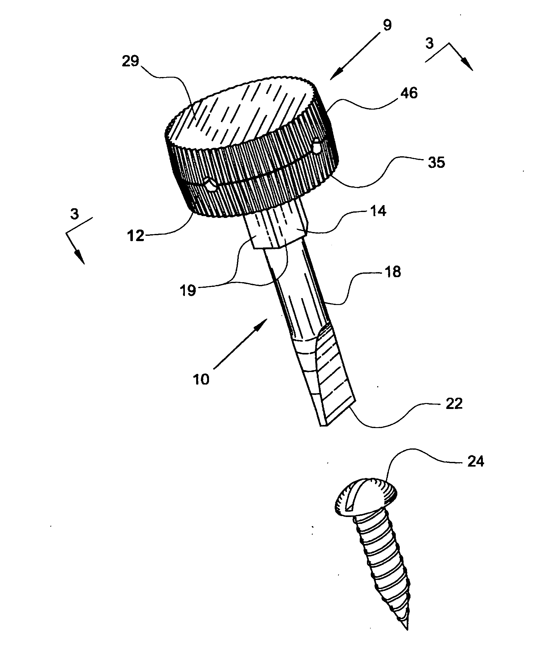
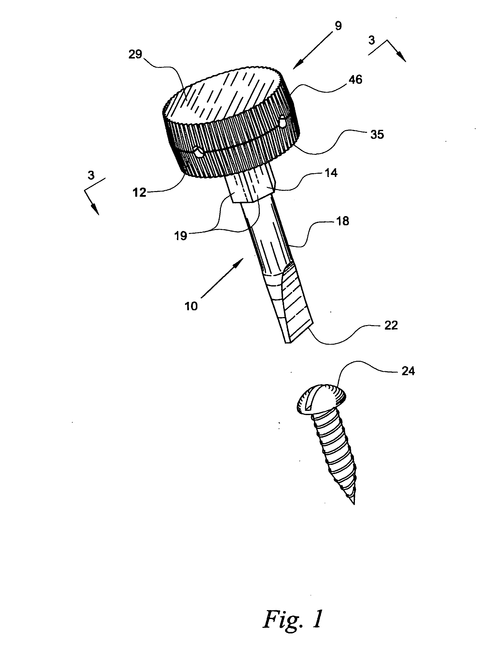
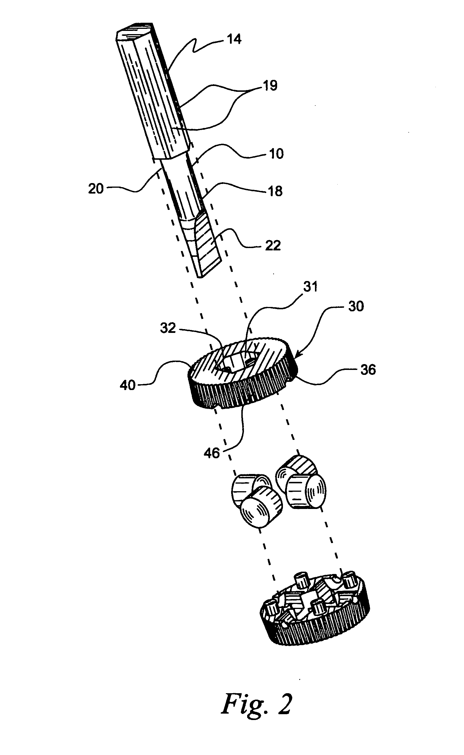
[0027] The present invention provides for the magnetic holding and mechanical rotation of objects such as tool bits or threaded fasteners or nuts by means of magnetic rings or annuluses. The objects (tool bits, fasteners, nuts, etc. . . .) are slidably held in central cavities defined by the annuluses. The cross section configuration of the central cavities match those of the objects with which the annuluses are in slidable communication.

[0028] The invented devices are adapted to be coaxially stacked together so as to provide a construct defining an axial bore or channel. One of the openings to the bore may be capped (as depicted in FIG. 1), thus preventing the objects inside the cavities from extending entirely through the construct.

[0029] The peripheries of the rings (i.e. the outwardly-facing surfaces of the rings) define surface topographies (for example flutes) to facilitate rotatable manipulation of the device by fingers or by tools such as plyers, wrenches or chucks of powe...


PUM


Abstract

A tool is provided for slidably receiving, magnetically holding, and mechanically engaging fasteners, tool bits, and nuts. The tool comprises one or more magnetic annuluses in stacked relation to each other. The tool defines an inner periphery that matches the shape of the fastener, bit, or nut. The tool further comprises an outer periphery adapted to be grasped by a hand or a tool so that a mechanical torque applied to the outer periphery of the annulus, which results in a mechanical torque applied to the fastener, bit, or nut.

Description

FIELD OF THE INVENTION [0001] The present invention relates to the field of tools and tool bits and more specifically, the present invention relates to the field of hand-held tools that utilize a magnetic force to hold tool bits, fasteners, and nuts. BACKGROUND OF THE INVENTION [0002] A bane of existence for many tradesman is separation of screw head or other fastener from a screwdriver tip or other bit during screw installation. Many tools use magnetization to hold a tool bit and a fastener together during driving operations. A typical arrangement is where a magnet is positioned near to or at the driving end of a screw driver's shank. The magnet imparts a magnetization to the tool bit which in turn attracts a ferrous fastener, such as a metal screw. The magnet is often lodged in a socket or a chuck at the tip of the shank; see for instance, U.S. Pat. No. 5,941,139 (Vodehnal); U.S. Pat. No. 5,913,596 (Lin); and U.S. Pat. No. 5,603,248 (Eggert et. al). [0003] These designs have the d...

Claims


Application Information

Patent Timeline
Patent Type & Authority Applications(United States)
IPC IPC(8): B25B23/10B25B23/08
CPCB25B23/12B25B15/02
Inventor KOZAK, BURTONKOZAK, IRA
Owner COMBINED PRODS
Learn More