
Belt-driven robot having extended Z-axis motion

a belt-driven robot and z-axis technology, applied in the field of belt-driven robots, can solve the problems of imposing limitations on the height of the robot, limiting the range of the robot, and imposing weight, size, complexity and rang

Active Publication Date: 2008-02-21
GENMARK AUTOMATION
View PDF16 Cites 25 Cited by
  • Summary
  • Abstract
  • Description
  • Claims
  • Application Information

AI Technical Summary

Problems solved by technology

Issues that are of concern in these types of robots include weight, size, complexity, and range.
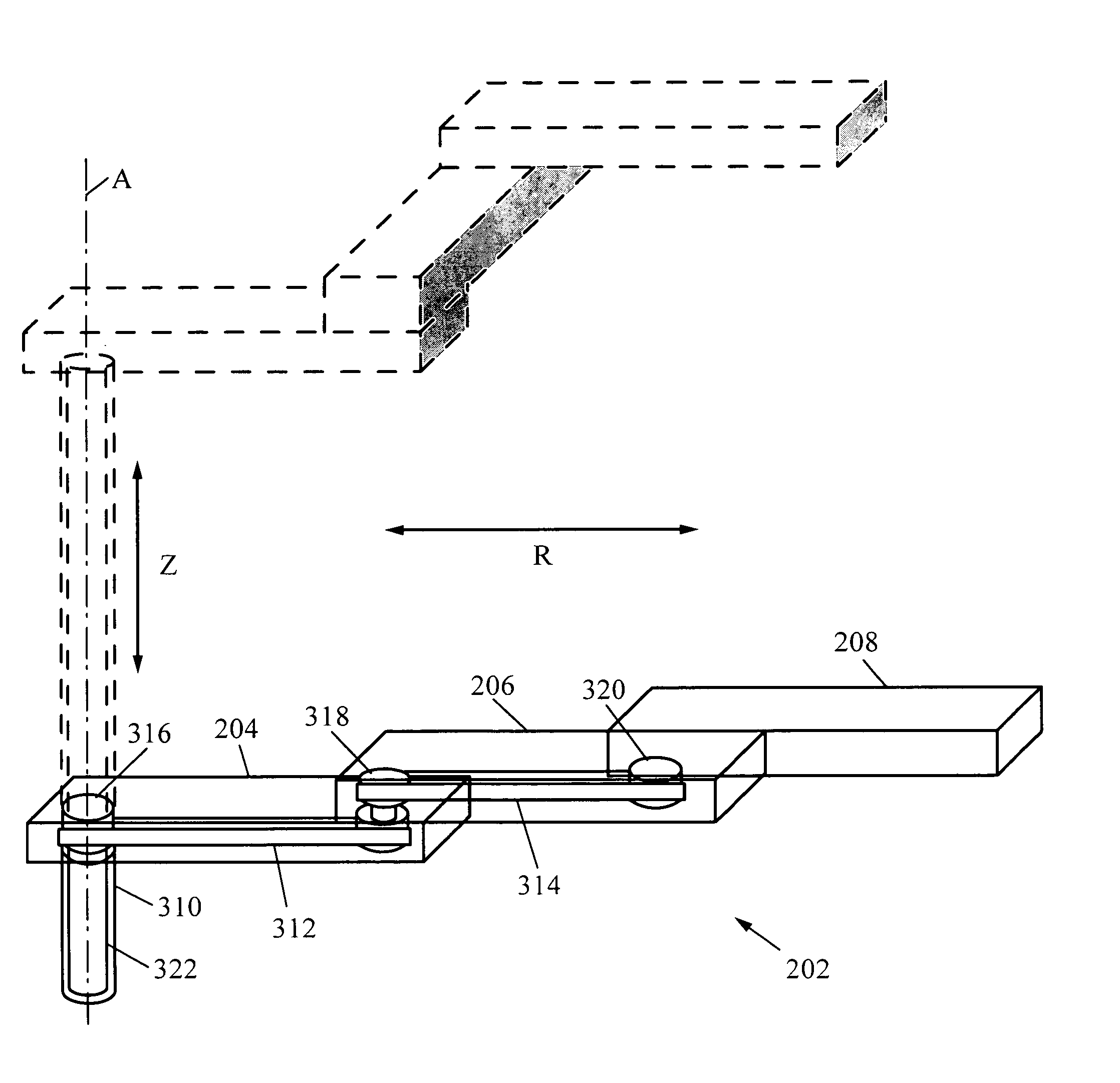
This imposes limitations on the robot height, which translate to limitations on robot range in the Z direction.
However, the translation module 461 is very heavy and cumbersome, and introduces significant amounts of inertia to the system.
One reason for this is that typically such a module relies on a ball screw 475, which itself is heavy difficult to manipulate.
The use of the translation module 461 therefore detracts from system speed, longevity, and overall performance while raising its cost and complexity.
Nonetheless, such an arrangement remains fairly constrained in its range, and requires expansion in the radial direction (R) to accommodate the additional collapsible supports 473, and is therefore cumbersome and tremendously complex.

Method used


Image

  • Belt-driven robot having extended Z-axis motion
  • Belt-driven robot having extended Z-axis motion
  • Belt-driven robot having extended Z-axis motion

Examples


Embodiment Construction

[0032]Embodiments of the present invention are described herein in the context of robots used for substrate transport in semiconductor processing. Those of ordinary skill in the art will realize that the following detailed description of the present invention is illustrative only and is not intended to be in any way limiting. Other embodiments of the present invention will readily suggest themselves to such skilled persons having the benefit of this disclosure. Reference will now be made in detail to implementations of the present invention as illustrated in the accompanying drawings. The same reference indicators will be used throughout the drawings and the following detailed description to refer to the same or like parts.

[0033]In the interest of clarity, not all of the routine features of the implementations described herein are shown and described. It will, of course, be appreciated that in the development of any such actual implementation, numerous implementation-specific decisi...


PUM


Abstract

A robot has a robot arm, a support structure, and a movable platform. The platform includes a cantilevered member coupled to a guide of the support structure such that motion of the platform is directed along a first direction. The robot further includes first and second timing belts having portions that extend along the first direction and that are disposed on opposite sides of the cantilevered member, and first and second shafts movable with the movable platform. The shafts are coupled to the respective timing belts, to the robot arm such that rotation of the first shaft imparts angular motion to the robot arm and rotation of the second shaft imparts radial motion. The robot also includes a third timing belt to which the platform is coupled and by which it is moved. Motors are provided that impart movement to the timing belts.

Description

CROSS-REFERENCE TO RELATED APPLICATIONS[0001]This application is a continuation-in-part of U.S. patent application Ser. No. 11 / 478,005, entitled “Robot with Belt-Drive System,” filed on Jun. 28, 2006.BACKGROUND OF THE INVENTION[0002]1. Field of the Invention[0003]The invention relates to robots used for substrate transport in semiconductor processing.[0004]2. Description of the Related Art[0005]Robots are commonly used in semiconductor processing environments, in order to transport substrates such as wafers to and from storage locations or various processing stations. The highly repetitive nature of the motions involved and the speeds required for high throughput make robots ideal candidates for these tasks. The types of motions of which these types of robots are capable vary. Typically, a robot 451 shown in FIG. 13, which has a robot body 453 and a robot arm 455 extending from the robot body will exhibit angular (θ), radial (R) and Z motions in a cylindrical coordinate system. As s...

Claims


Application Information

Patent Timeline
Patent Type & Authority Applications(United States)
IPC IPC(8): B25J17/00
CPCB25J9/042B25J9/104B25J18/04H01L21/67742Y10T74/20341Y10T74/20329Y10T74/20305Y10T74/20323H01L21/67766B25J9/0021
Inventor TODOROV, ALEXANDER
Owner GENMARK AUTOMATION
Learn More