
Methods of using high intensity focused ultrasound to form an ablated tissue area containing a plurality of lesions

a tissue area and high intensity technology, applied in ultrasonic/sonic/infrasonic diagnostics, therapy, applications, etc., can solve the problems of coagulative necrosis, complex surgical maze procedure, and tissue damage, and achieve the effect of easy positioning, manipulation, stabilization and/or holding an organ

Inactive Publication Date: 2008-02-14
MEDTRONIC INC
View PDF98 Cites 1021 Cited by
  • Summary
  • Abstract
  • Description
  • Claims
  • Application Information

AI Technical Summary

Benefits of technology

The present invention is a method of tissue ablation using guidance or navigation. The invention allows for the use of ablation to treat various conditions such as atrial fibrillation (AF) and other arrhythmias. The invention uses ablation to create lesions in the heart to modify the substrate and prevent the maintenance of AF. The invention also allows for the use of a variety of ablation devices and techniques, including the use of a phased array for ablation. The invention provides a system for easily positioning and manipulating the ablation device, as well as a method for controlling the ablating energy to create precise and consistent lesions. Overall, the invention provides a more effective and safe way to treat AF and other arrhythmias.

Problems solved by technology

Thermal effects include heating of the tissue; and, when the tissue is heated to a sufficiently high temperature, tissue damage such as coagulative necrosis can be produced.
Occasionally, these electrical signals do not function properly, thereby causing heart arrhythmias.
Although successful in treating AF, the surgical Maze procedure is quite complex and is currently performed by a limited number of highly skilled cardiac surgeons in conjunction with other open-heart procedures.
Irrigated RF epicardial ablation approaches allow the heat to penetrate deeper into the tissue, but tend to be limited in depth.
Without sufficient space and field of view, it is difficult for the surgeon to recognize the anatomical location and identity of structures viewed on the video display.
The requirement for space surrounding the working field has the effect of limiting the regions which can be safely and confidently accessed by minimally invasive endoscopic techniques.
For example, it is very difficult for the surgeon to endoscopically visualize the passage of instruments through the spaces posterior to and around portions of the heart such as the transverse and oblique sinuses.
Due to these limitations, some procedures have not been attempted using minimally invasive endoscopic techniques.

Method used


Image

  • Methods of using high intensity focused ultrasound to form an ablated tissue area containing a plurality of lesions
  • Methods of using high intensity focused ultrasound to form an ablated tissue area containing a plurality of lesions
  • Methods of using high intensity focused ultrasound to form an ablated tissue area containing a plurality of lesions

Examples


Embodiment Construction

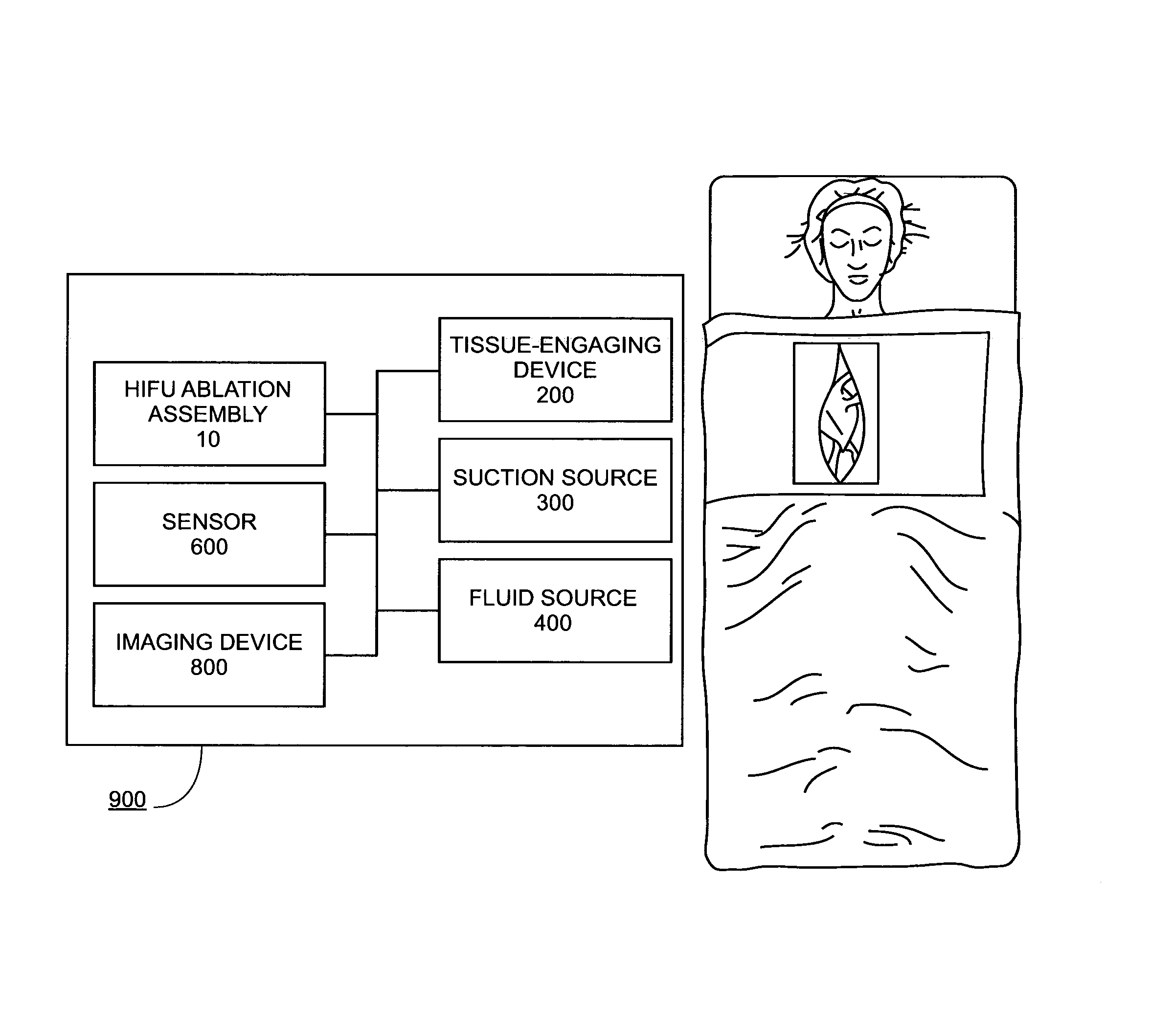
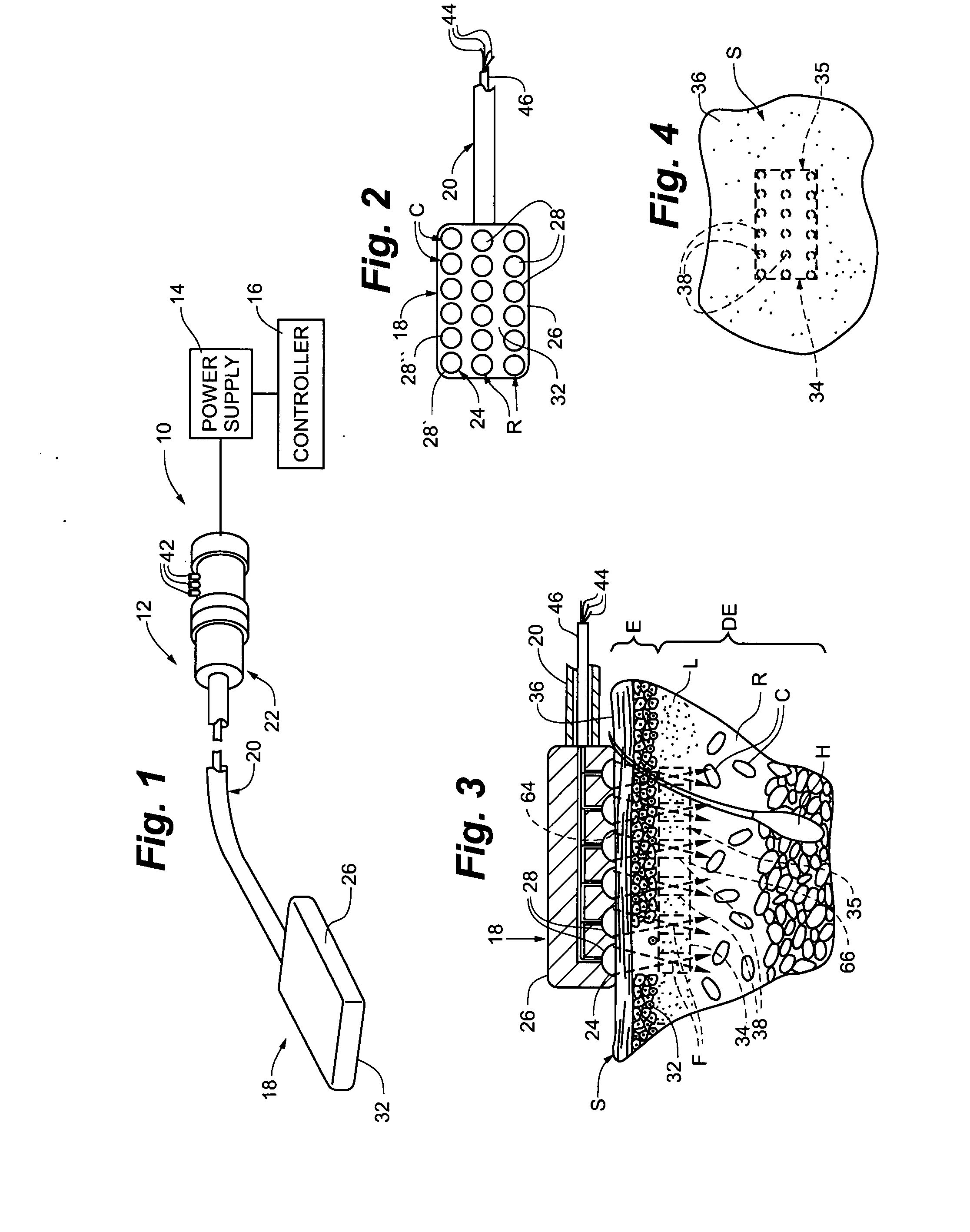
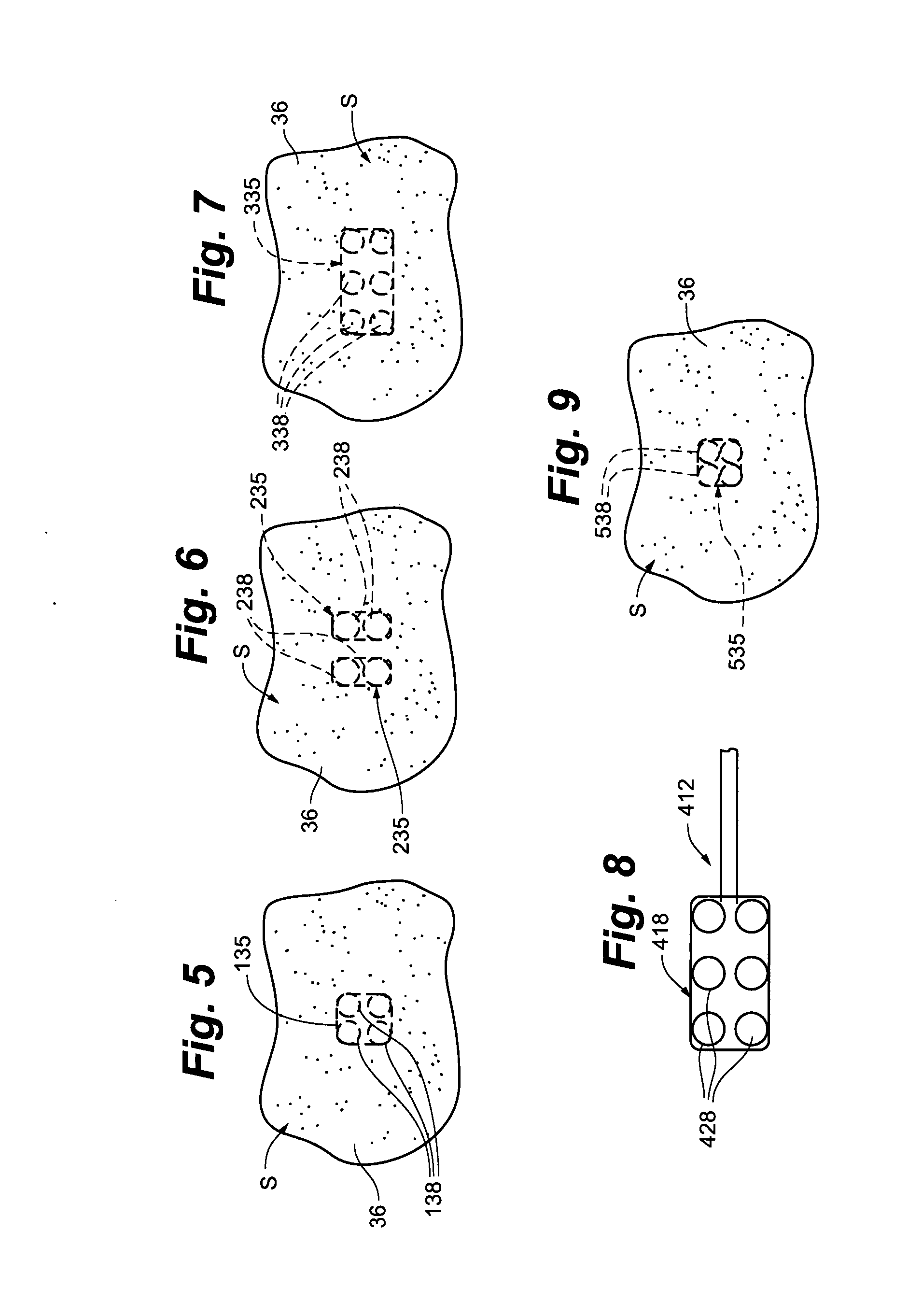
[0072] One embodiment of an ablation or stimulation assembly or system 10 for use in the methods of the present invention is illustrated in FIG. 1 and is similar to the HIFU stimulation assembly described in prior U.S. patent application Ser. No. 10 / 464,213 and U.S. patent application Ser. No. 10 / 600,871, the disclosures of which are incorporated herein by reference. The high intensity focused ultrasound ablation or stimulation assembly or system 10 includes a focused ultrasound ablation or stimulation device 12, a power supply 14 and a controller 16. The focused ultrasound ablation or stimulation device 12 is similar to that described in U.S. patent applications Ser. Nos. 10 / 464,213 and 10 / 600,871 and includes a focused ultrasound emitting member 18, an elongate handle shaft or body 20 having a distal end at which the ultrasound emitting member is disposed and a handle or handpiece 22 coupled to a proximal end of the handle shaft 20. As shown in FIGS. 2 and 3, the ultrasound emitti...


PUM


Abstract

A device and method for ablating tissue is disclosed comprising the steps of acquiring an anatomical image of a patient, correlating the image to the patient, guiding an ablating member within the patient while tracking the position of the ablating member in the patient, positioning the ablating member in a desired position to ablate tissue, emitting ablating energy from the ablating member to form an ablated tissue area and removing the ablating member from the patient.

Description

CROSS REFERENCE TO RELATED APPLICATIONS [0001] This application claims priority to U.S. Provisional Patent Application No. 60 / 808,306, filed May 25, 2006, the disclosure of which is incorporated herein by reference. [0002] This application is also a continuation-in-part of U.S. patent application Ser. No. 11 / 298,282 filed Dec. 9, 2005, which is a continuation-in-part of U.S. patent application Ser. No. 11 / 128,686 filed May 13, 2005, which claims the benefit of U.S. Provisional Patent Application Ser. No. 60 / 571,182 filed on May 14, 2004, the disclosures of which are incorporated herein by reference in their entirety. [0003] This application is also a continuation-in-part of U.S. application Ser. No. 11 / 184,398, filed Jul. 19, 2005, which is a continuation of U.S. application Ser. No. 10 / 464,213, filed Jun. 18, 2003, now U.S. Pat. No. 6,936,046, which is a continuation of U.S. application Ser. No. 09 / 629,194, filed Jul. 31, 2000, now U.S. Pat. No. 6,595,934, which is a continuation-i...

Claims


Application Information

Patent Timeline
Patent Type & Authority Applications(United States)
IPC IPC(8): A61B18/04
CPCA61B19/5244A61B2018/00291A61B2019/5251A61N2007/0078A61B2019/5278A61N7/022A61B2019/5276A61B8/4281A61B2090/3782A61B34/20A61B2034/2051A61B2090/378A61B2017/320078A61B2017/320069A61B2017/32007A61B2017/320071A61N7/02
Inventor HISSONG, JAMES B.STEWART, MARK T.FRANCISCHELLI, DAVID E.KEOGH, JAMES R.SKARDA, JAMES R.LEE, HOTAIKSMITH, NADINE B.
Owner MEDTRONIC INC
Learn More