
Portable terminal

Inactive Publication Date: 2008-02-14
FUJITSU TOSHIBA MOBILE COMM LTD
View PDF7 Cites 46 Cited by
  • Summary
  • Abstract
  • Description
  • Claims
  • Application Information

AI Technical Summary

Problems solved by technology

However, for example, when the cellular phone is kept in a bag, blinking of the LED or the like does not allow the user to notice the missed call.

Method used


Image

  • Portable terminal
  • Portable terminal
  • Portable terminal

Examples


Embodiment Construction

[0016]An embodiment of the present invention will be described below with reference to the accompanying drawing.

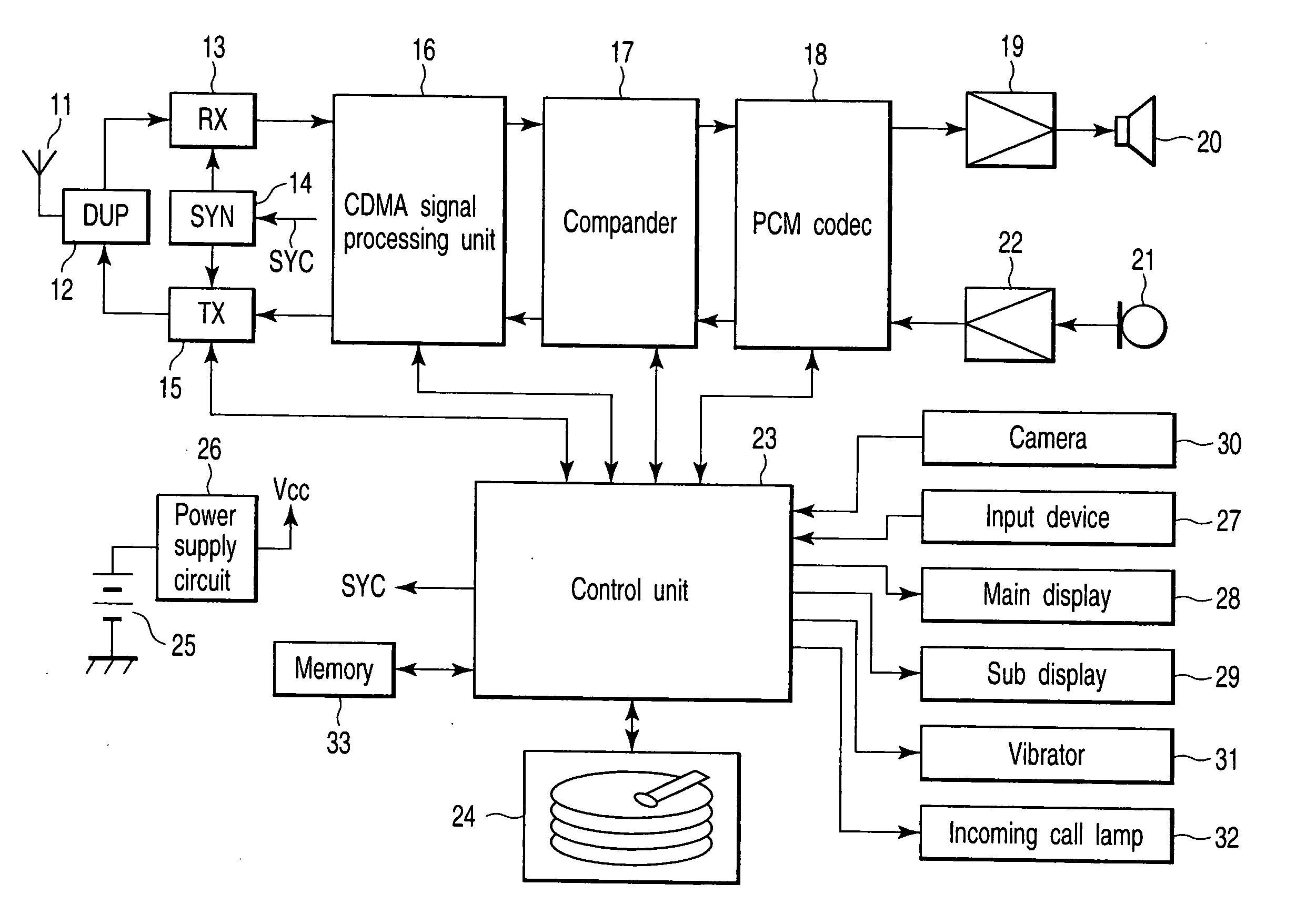
[0017]FIG. 1 is a block diagram showing the arrangement of a cellular phone as a portable terminal according to an embodiment of the present invention.

[0018]A radio signal transmitted from a base station (not shown) is received by an antenna 11, and is input to a reception circuit (RX) 13 via an antenna duplexer (DUP) 12. The reception circuit 13 frequency-converts (down-converts) the received radio signal to an intermediate-frequency signal by mixing it with a local oscillation signal output from a frequency synthesizer (SYN) 14. The reception circuit 13 then quadrature-demodulates this down-converted intermediate-frequency signal to output a received baseband signal. Note that the frequency of the local oscillation signal generated by the frequency synthesizer 14 is designated by a control signal SYC from a control unit 23.

[0019]The received baseband signal is input to a...


PUM


Abstract

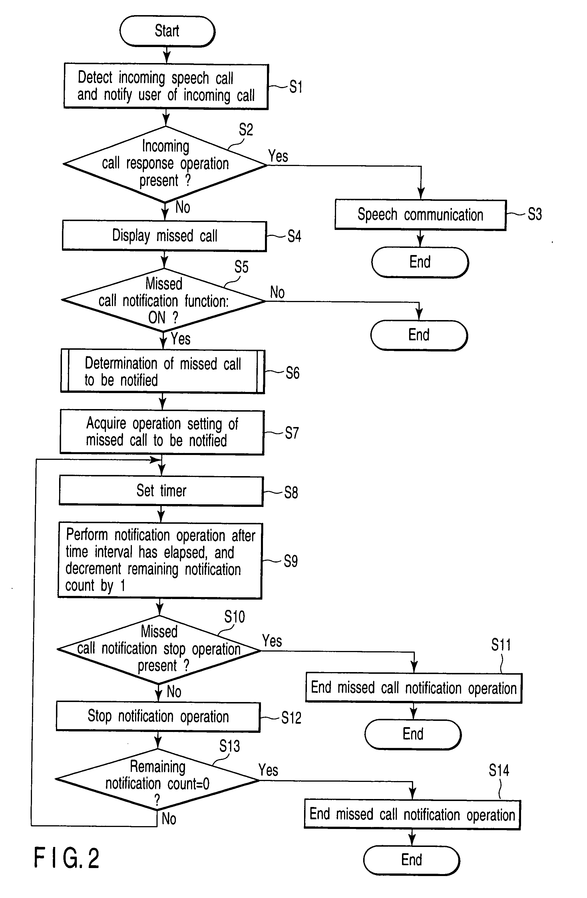
A portable terminal includes an output device configured to output a ringing tone, a vibrator configured to generate vibration, and a first controller configured to detect a missed call indicating that an incoming call response operation is not performed, and a second controller coupled to the first controller. The second controller is configured, if the first controller detects the missed call, to notify a missed call notification at predetermined time intervals by at least one of the ringing tone output from the output device and the vibration generated by the vibrator, the missed call notification indicating that a response operation for the missed call is not performed.

Description

CROSS-REFERENCE TO RELATED APPLICATIONS[0001]This application is based upon and claims the benefit of priority from prior Japanese Patent Application No. 2006-220367, filed Aug. 11, 2006, the entire contents of which are incorporated herein by reference.BACKGROUND OF THE INVENTION[0002]1. Field of the Invention[0003]The present invention relates to a portable terminal.[0004]2. Description of the Related Art[0005]Upon reception of an incoming speech call or email, a cellular phone as the portable terminal notifies a user of this reception result by generating a ringing tone or vibration. However, for example, when the user puts the cellular phone in a bag or when the cellular phone is away from the user, the user sometimes does not notice the incoming call. In consideration of such situation, the current cellular phone generally has a function of notifying the user of a missed call by blinking an incoming call lamp such as an LED.[0006]However, for example, when the cellular phone is...

Claims


Application Information

Patent Timeline
IPC IPC(8): H04B1/38H04M1/00
CPCH04M1/57H04M19/047H04M19/04
Inventor ARISAWA, YUKIHIKO
Owner FUJITSU TOSHIBA MOBILE COMM LTD
Learn More