
Feedback-controlled coherent optical receiver with electrical compensation/equalization

a coherent optical receiver and electrical compensation technology, applied in the field of optical communication systems, can solve the problems of inability to fine control and optimize, and the implementation of phase/frequency lock is not amenable to fine control and optimization, and achieve the effect of reducing cost and high reliability

Active Publication Date: 2008-02-14
DISCOVERY SEMICON
View PDF33 Cites 35 Cited by
  • Summary
  • Abstract
  • Description
  • Claims
  • Application Information

AI Technical Summary

Benefits of technology

[0023] An object of the invention is to provide a highly reliable, multifunctional optical coherent receiver of reduced cost.
[0025] Another object of the invention is to provide a fiber-based optical generation / management subsystem and integrated optical control circuit-based designs for minimizing weight and volume, while enhancing reliability of the associated optical coherent receiver.
[0026] Another object of the invention is to provide integrated circuit-based designs for minimizing the weight and volume of the opto-electronic and RF subsystems, while enhancing reliability of the associated optical coherent receiver.

Problems solved by technology

However, the following operational drawbacks generally exist for these systems: 1.
The phase / frequency lock implementation is not amenable to fine control and optimization.
These drawbacks in a conventional coherent receiver can significantly impair both intrinsic

Method used


Image

  • Feedback-controlled coherent optical receiver with electrical compensation/equalization
  • Feedback-controlled coherent optical receiver with electrical compensation/equalization
  • Feedback-controlled coherent optical receiver with electrical compensation/equalization

Examples


Embodiment Construction

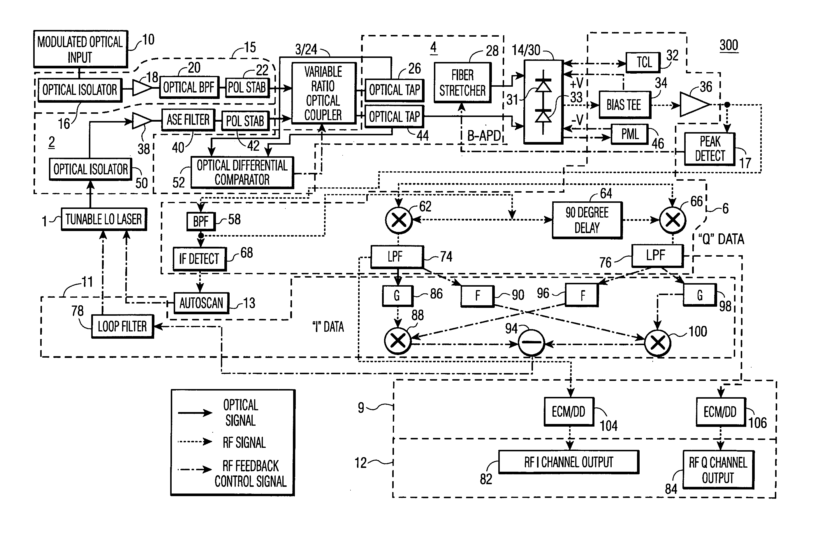
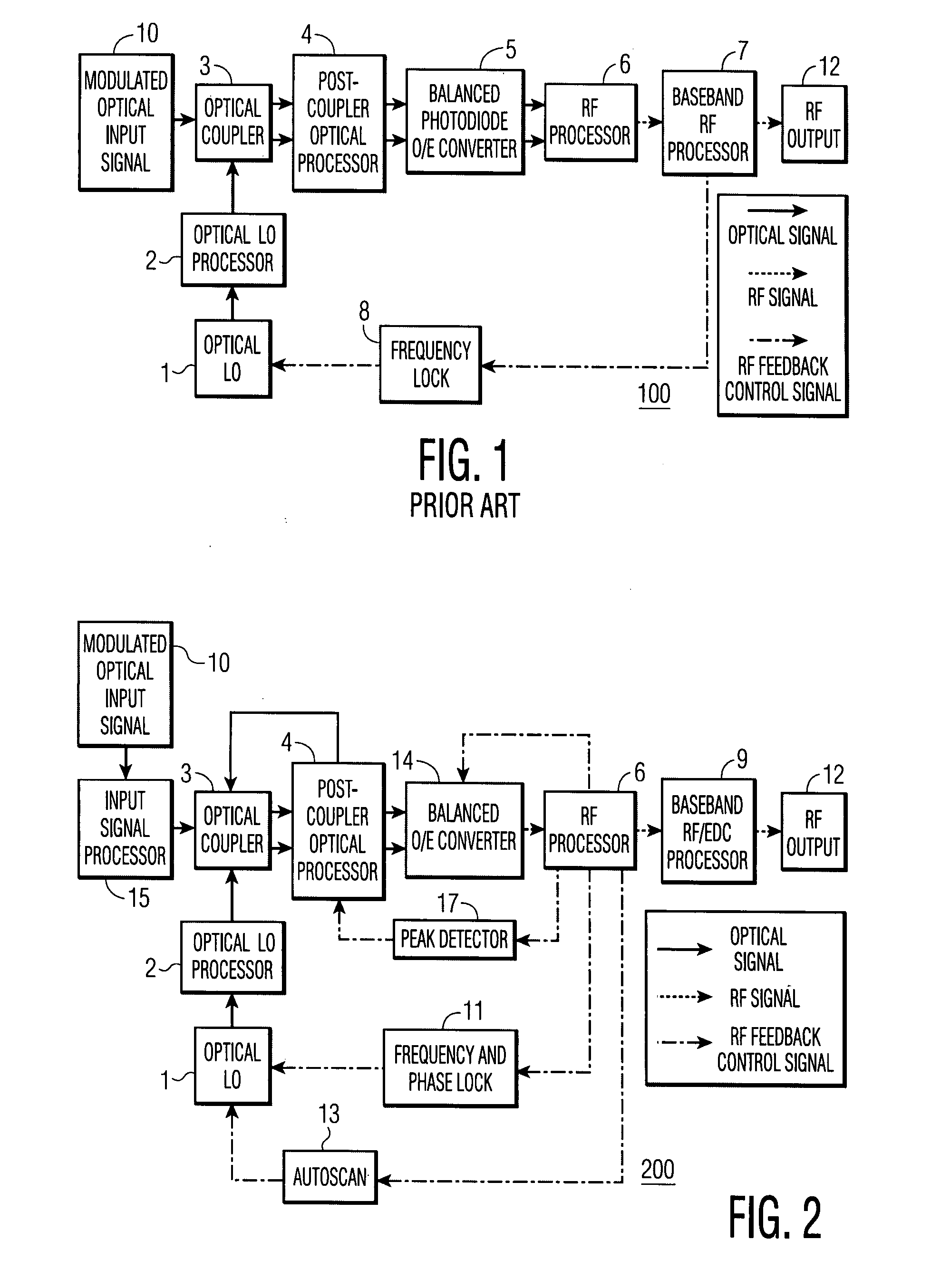
[0046] A brief description of operational drawbacks of a coherent receiver system as shown in FIG. 1 was previously provided. With further reference to FIG. 1, a known coherent receiver system is shown in the block schematic diagram of FIG. 1. As shown, the prior coherent receiver 100 includes an optical local oscillator (LO) 1 for outputting an optical signal to an optical local oscillator processor system 2, which in turn drives an optical coupler 3. The optical coupler 3 serves to receive a modulated optical input signal 10, and feed or couple the same to a post coupler optical processing circuit or network 4, which in turn couples the processed signal to a balanced photodiode and RF (radio frequency) amplifier 5. The RF output signal from the balance photodiode amplifier 5 is fed to an RF processing circuit 6, which in turn feeds an output signal to a baseband RF processing circuit 7, the output of which is connected both to an RF Output terminal or connector 12, and also to a f...


PUM


Abstract

An optical coherent receiver in one embodiment has a heterodyne configuration, and in another embodiment has a homodyne configuration, in each configuration employs multiple feedback signaling and analog / digital processing to optimize response to a modulated optical input signal, the provision of both individual RF I and RF Q channel outputs.

Description

RELATED APPLICATION [0001] The present Application is related to co-pending Provisional Application Ser. No. 60 / 781,233, filed Mar. 10, 2006, for “Optical Coherent Receiver System,” takes priority therefrom, and incorporates by reference the teachings thereof to the extent they do not conflict herewith. The related Application has the same inventorship and assignee as the present Application. GOVERNMENT INTEREST [0002] The US Government has a paid-up license in this invention and the right in limited circumstances to require the patent owner to license others on reasonable terms as provided for by the terms of Grant No. MDA904-03C-0462, awarded by the NSA (National Security Agency).FIELD OF THE INVENTION [0003] The present invention is generally related to optical communication systems, and more particularly to optical coherent receivers for detecting optical signals. BACKGROUND OF THE INVENTION [0004] Coherent optical detection was considered intensively for fiber optics in the 80'...

Claims


Application Information

Patent Timeline
IPC IPC(8): H04B10/06H04B10/43
CPCH04B10/616H04B10/615H04B10/64H04B10/63H04B10/613H04B10/6164
Inventor BECKER, DONALD A.MOHR, DANIEL R.WREE, CHRISTOPH T.JOSHI, ABHAY M.
Owner DISCOVERY SEMICON
Learn More