
Systems and Methods for Providing Maximum Photovoltaic Peak Power Tracking

Inactive Publication Date: 2008-02-14
AMBIENT CONTROL SYST
View PDF5 Cites 216 Cited by
  • Summary
  • Abstract
  • Description
  • Claims
  • Application Information

AI Technical Summary

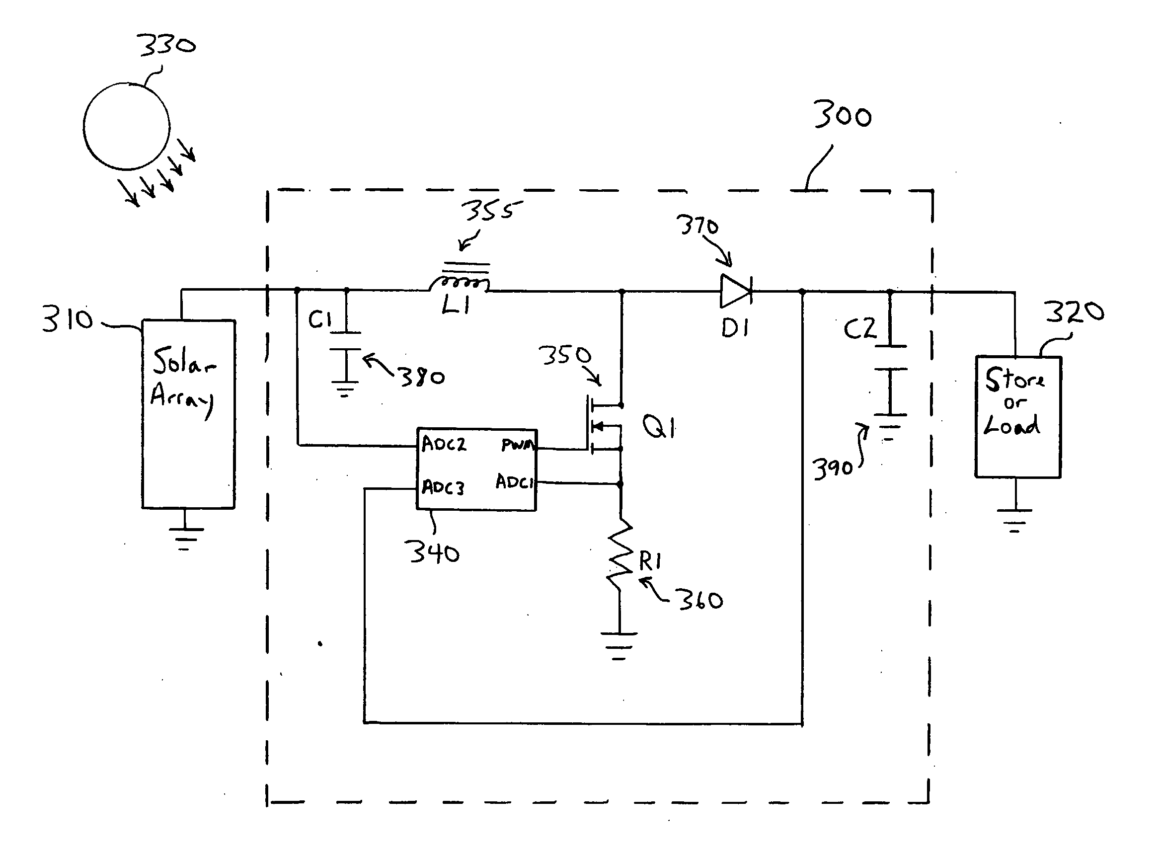
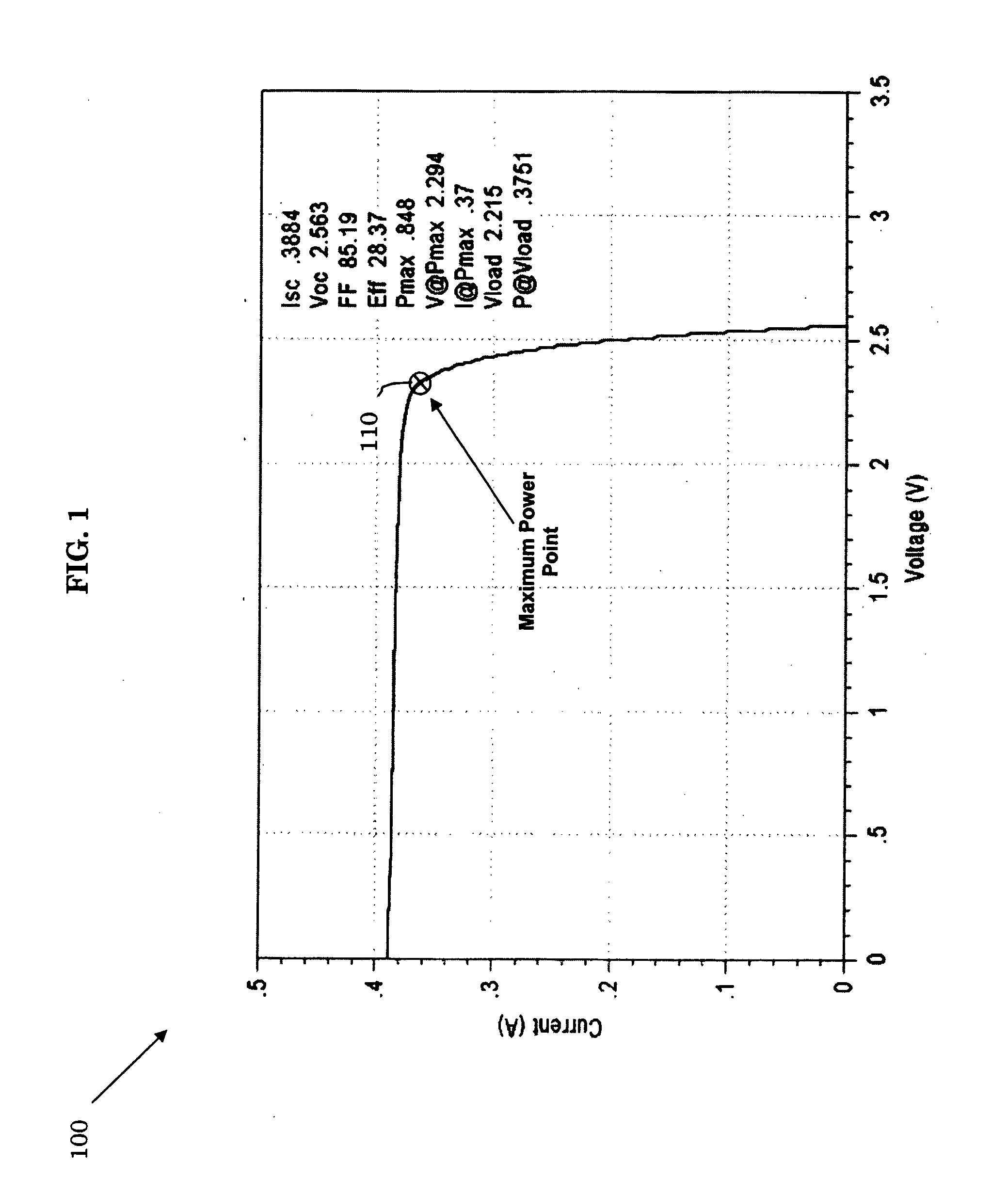
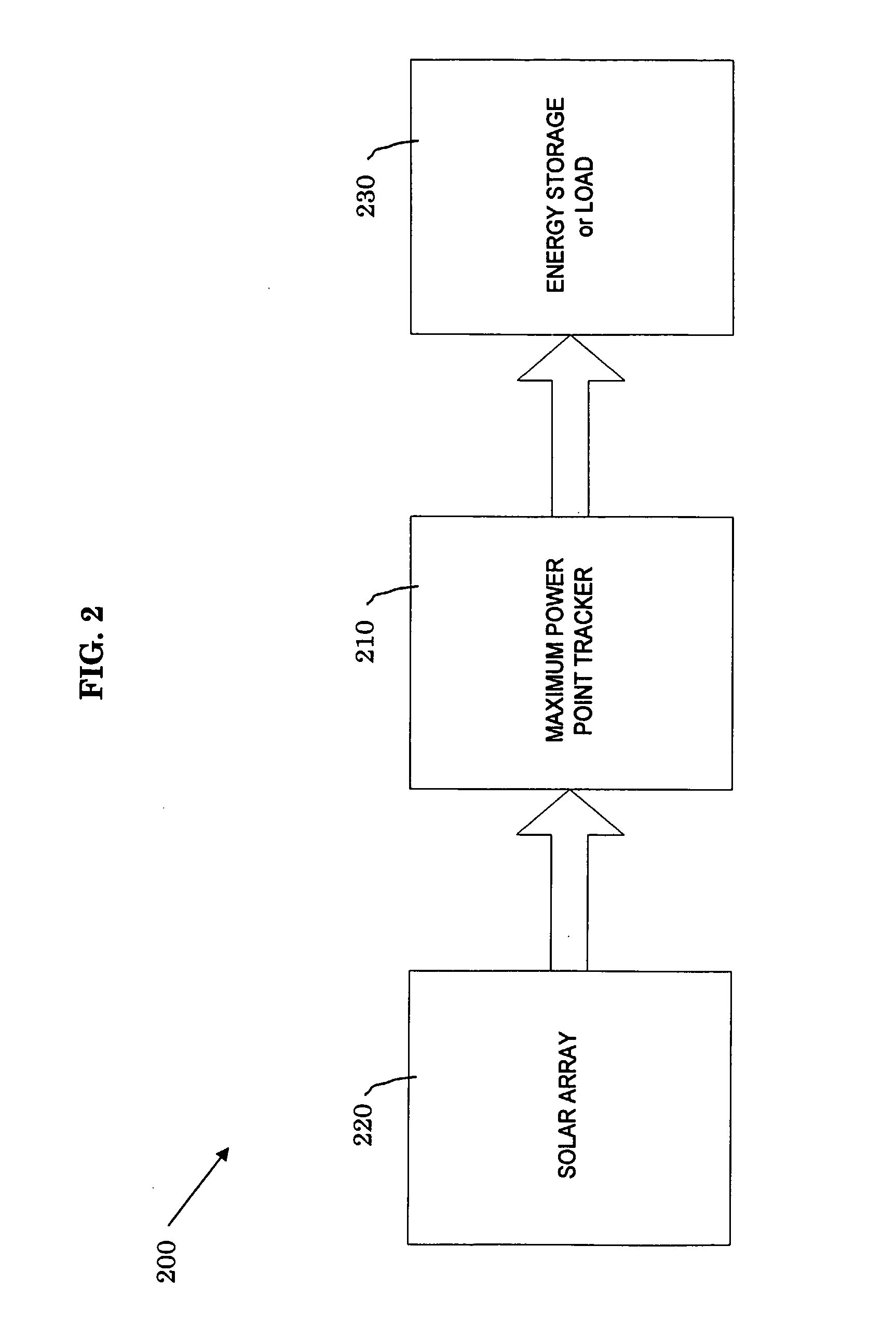
Benefits of technology

[0004] Disclosed and claimed herein are systems and methods for providing maximum photovoltaic peak power tracking. In one embodiment, a method includes executing a power control algorithm, providing a switching frequency or pulse width based on the power control algorithm to a high speed switching circuit, and

Problems solved by technology

However, electromechanical systems have not been appropriate for low power solar arrays or small installations.
Electronic systems, on the other hand, are neither efficient nor cost effective at relatively low power levels (e.g., below 300 Watts).

Method used


Image

  • Systems and Methods for Providing Maximum Photovoltaic Peak Power Tracking
  • Systems and Methods for Providing Maximum Photovoltaic Peak Power Tracking
  • Systems and Methods for Providing Maximum Photovoltaic Peak Power Tracking

Examples


Embodiment Construction

[0010] One aspect of the invention is to increase the available power for low-power, remote equipment or equipment that is required to operate without external power connections. In one embodiment, a micropower Maximum Power Point Tracker (μMPPT) suitable for use in low power applications is used to maximize the power output for a solar-power cell array.

[0011] In one embodiment, a μMPPT comprises an electrical circuit which includes a microprocessor / microcontroller used to execute the μMPPT control algorithm, and a modulator controller to control the pulse width or frequency to a high speed switch, such as a metal-oxide semiconductor field-effect transistor (MOSFET). In addition, the electrical circuit may include an analog-to-digital (A / D) converter, either external to or as part of the microprocessor / microcontroller, usable to measure the input voltage from a connected solar array, the current through an inductor of the circuit, and the voltage of an attached energy store or load...


PUM


Abstract

A micropower Maximum Power Point Tracker (μMPPT) suitable for use in low power applications to maximize the power output for a solar-power cell array. In one embodiment, a μMPPT comprises an electrical circuit which includes a microprocessor / microcontroller used to execute the μMPPT control algorithm, and a modulator controller to control the pulse width or frequency to a high speed switch. In addition, the electrical circuit may include an analog-to-digital (A / D) converter usable to measure the input voltage from a connected solar array, the current through an inductor of the circuit, and the voltage of an attached energy store / load. In another embodiment, the μMPPT may operates in at least two modes depending on the energy store / loads conditions.

Description

CROSS REFERENCE TO RELATED APPLICATION [0001] This application is related to and claims priority from the U.S. provisional patent application having application No. 60 / 582,075, filed on Jun. 24, 2004, and is the National Stage of International Application No. PCT / US2005 / 022509, filed Jun. 24, 2005.1. FIELD OF THE INVENTION [0002] The invention relates in general to power management, and in particular to a maximum power point tracker circuit used to improve photovoltaic module efficiency in solar-powered applications. 2. BACKGROUND [0003] Certain solar-powered systems, such as remote instrumentation packages, operate at relatively low power levels. In order to maximize the amount of power generated by photovoltaic modules, typical solar-powered systems have made use of a Maximum Power Point Tracker (MPPT). Currently available MPPT can be either electromechanical tracking system that point the solar array at the sun, and electronic controller system that adjust the apparent load on th...

Claims


Application Information

Patent Timeline
IPC IPC(8): G05F5/00
CPCY02E10/58G05F1/67H02M3/156Y02E10/56
Inventor GARMER, WILLIAM
Owner AMBIENT CONTROL SYST
Learn More