Paper feeding mechanism
a feeding mechanism and paper technology, applied in the direction of transportation and packaging, thin material processing, article separation, etc., can solve the problems of unsatisfactory paper feeding and folding, increase manufacturing cost, etc., and achieve the effect of reducing volume, eliminating ineffective component force, and smoothly feeding paper
- Summary
- Abstract
- Description
- Claims
- Application Information
AI Technical Summary
Benefits of technology
Problems solved by technology
Method used
Image


Examples
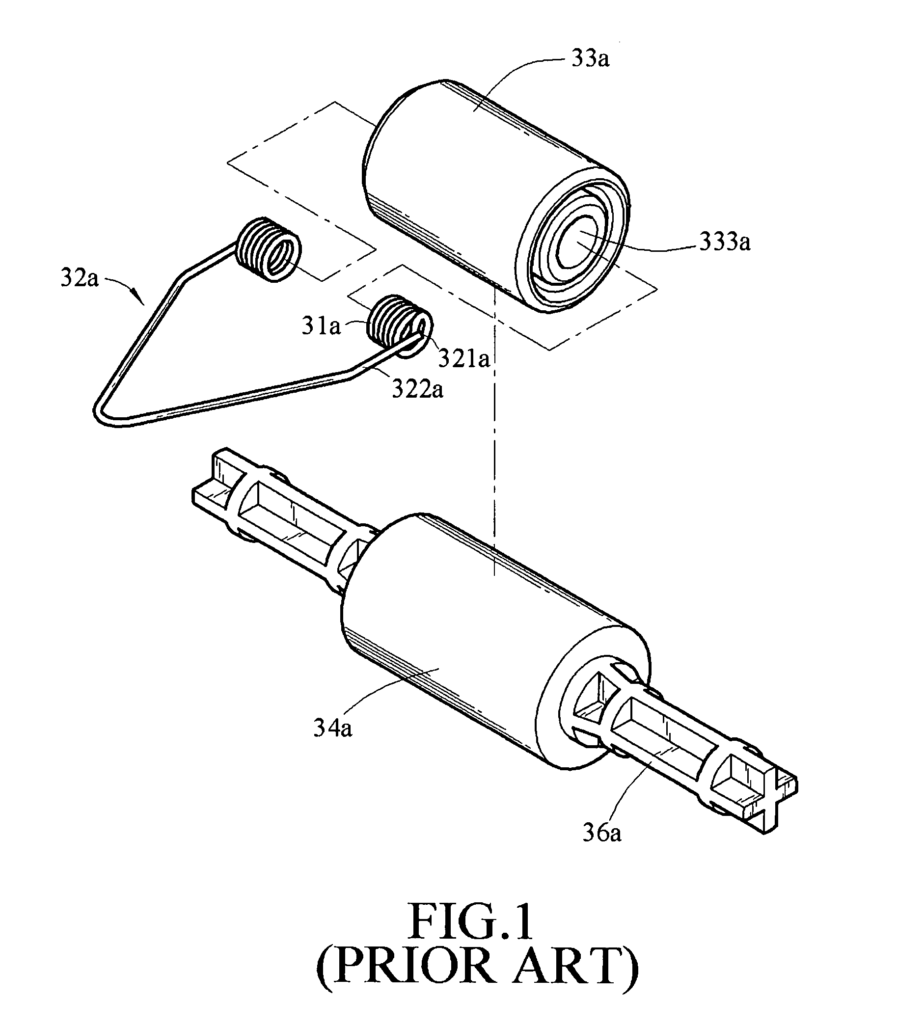
first embodiment
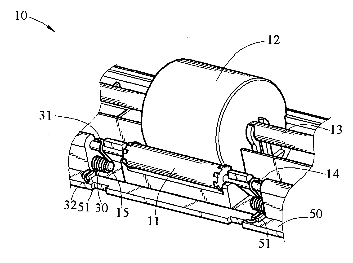
[0023]Please refer to FIG. 4 of an exploded structural view of a paper feeding mechanism 10 according to the present invention. As shown in FIG. 4, the paper feeding mechanism 10 includes a driven roller 11, an active roller 12, and a base 50. The base 50 has a driven roller 11 and a driven roller shaft 14. The driven roller 11 and the active roller 12 are disposed in correspondence with each other. The driven roller shaft 14 is disposed in the rotational axial direction of the driven roller 11 and passes through the driven roller 11, and a transmission shaft 13 passes through the active roller 12.
[0024]Further, two shafts 15 adjacent to one side of the driven roller shaft 14 are joined with the base 50. One of the two opposite ends of each shaft 15 is a free end, and the other is fixed on the base 50. Moreover, the shafts 15 are parallel to the axial direction of the driven roller shaft 14.
[0025]The paper feeding mechanism 10 also has a plurality of torsion elements 30 disposed bet...
second embodiment
[0028]Please refer to FIG. 6 of a combined structural view of the paper feeding mechanism 10 according to the present invention. As shown in FIG. 6, the two opposite ends of the shaft 15A are joined with the base 50, and a plurality of torsion elements 30 is coaxially connected to the shaft 15A.
[0029]Please refer to FIG. 7 of a schematic view of a position of a stopper according to the present invention. As shown in FIG. 7, a stopper 53 is further disposed on the base 50 of the present invention in a limited position adjacent to the driven roller shaft 14. When the driven roller 11 presses against the active roller 12, the driven roller 11 can only move in the limited position. The stopper 53 can confine the driven roller 11 moving within a limited range. The stopper 53 and the base 50 are integrated into one piece.
PUM
 Abstract
Description
Claims
Application Information
 - R&D
- Intellectual Property
- Life Sciences
- Materials
- Tech Scout
- Unparalleled Data Quality
- Higher Quality Content
- 60% Fewer Hallucinations
Browse by: Latest US Patents, China's latest patents, Technical Efficacy Thesaurus, Application Domain, Technology Topic, Popular Technical Reports.
© 2025 PatSnap. All rights reserved.Legal|Privacy policy|Modern Slavery Act Transparency Statement|Sitemap|About US| Contact US: help@patsnap.com