
Aircraft air conditioning system and method of operating an aircraft air conditioning system

a technology of air conditioning system and air conditioner, which is applied in the direction of air-treatment apparatus arrangement, transportation and packaging, energy-saving board measures, etc., and can solve the problem of changing the temperature of compressed air as well

Active Publication Date: 2008-02-07
LIEBHERR AEROSPACE LINDENBERG
View PDF13 Cites 34 Cited by
  • Summary
  • Abstract
  • Description
  • Claims
  • Application Information

AI Technical Summary

Benefits of technology

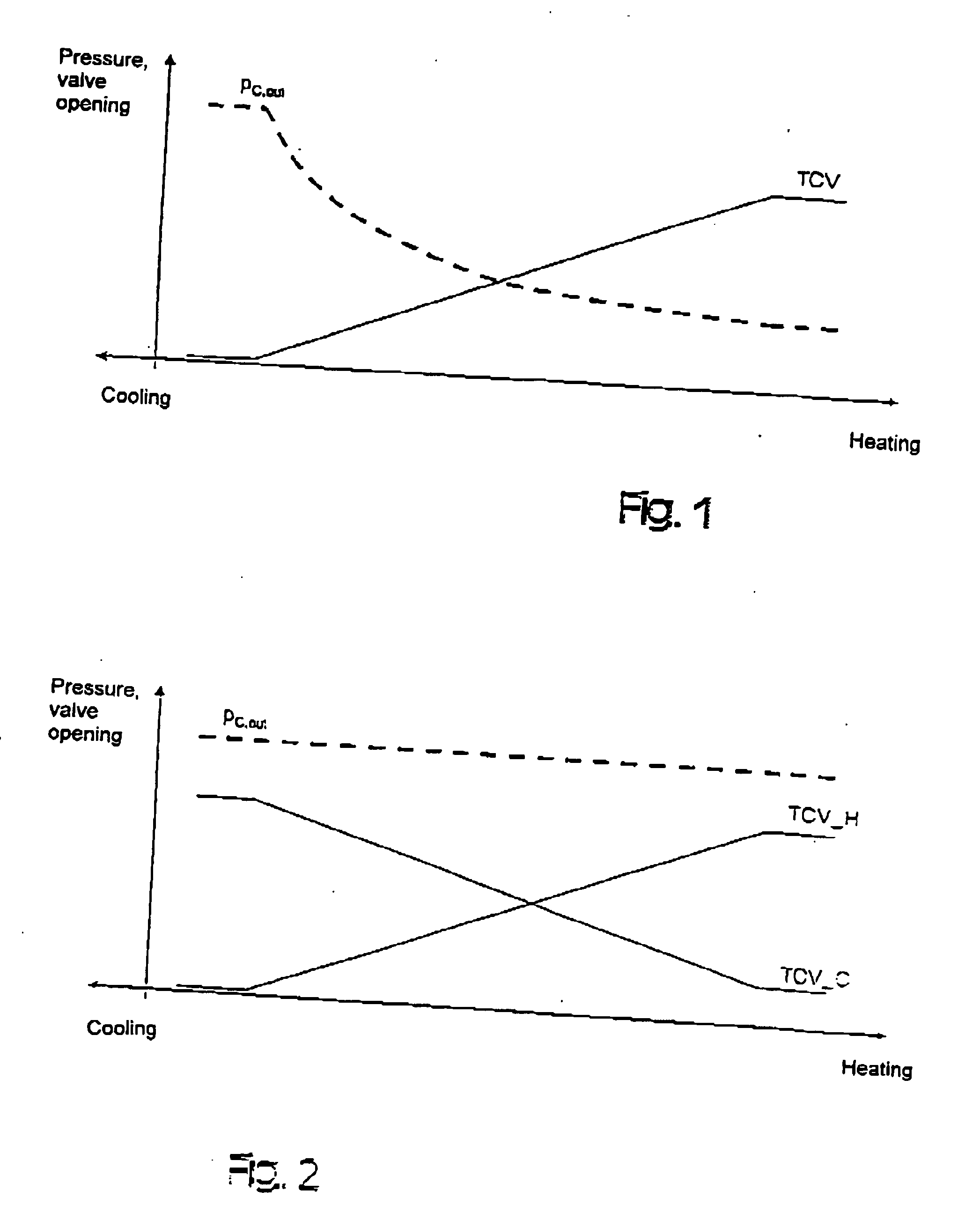
[0008] The unit is designed such that in the first operating mode, when the opening of the throttle means provided in the bypass conduit is increased, it effects a reduction of the opening of the throttle means provided in the first conduit and, inversely, when the opening of the throttle means provided in the bypass conduit is reduced, it effects an increase of the opening of the throttle means provided in the first conduit. Due to the creation of a throttle means in the mass flow, which is directed over the cooling means, it is possible to make the conditions at the compressor outlet such that the variation of the opening of the throttle means arranged in the bypass conduit does not or only insignificantly lead to a change in the level of the compressor outlet pressure. In this way, a constant reproducible connection between the valve position of the throttle means of the bypass conduit and the temperature of the air flow supplied to the mixing chamber or aircraft cabin can be achieved.

Problems solved by technology

A problem of electrically driven aircraft air conditioning systems for fresh air supply, air conditioning and pressurization consists in that with a specified mass flow rate, the pressure conditions on the compressor outlet side are changed due to the adjustment of the throttle means arranged in the bypass conduit, which in turn leads to the fact that the temperature of the compressed air is changed as well.

Method used


Image

  • Aircraft air conditioning system and method of operating an aircraft air conditioning system
  • Aircraft air conditioning system and method of operating an aircraft air conditioning system
  • Aircraft air conditioning system and method of operating an aircraft air conditioning system

Examples


Embodiment Construction

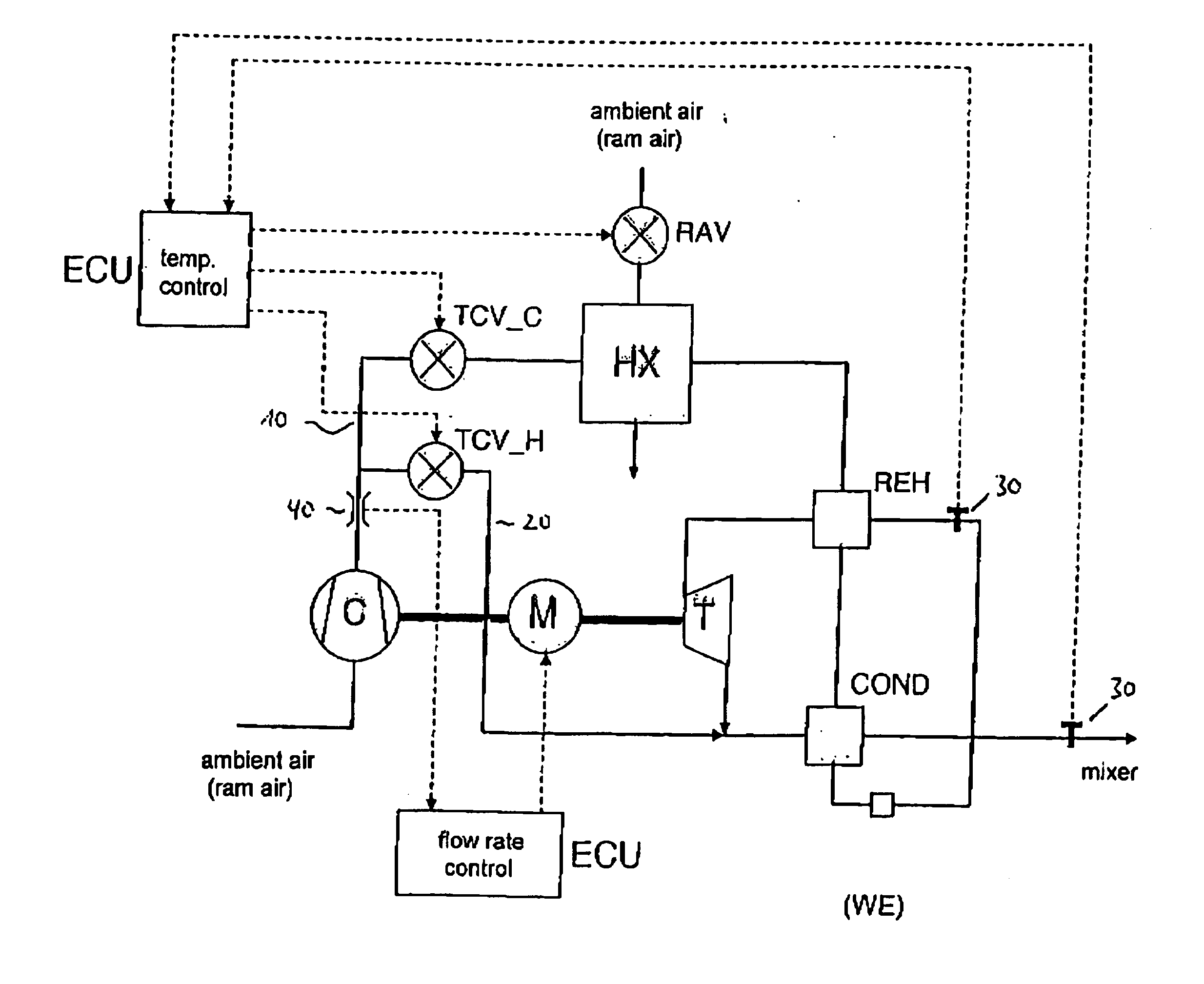
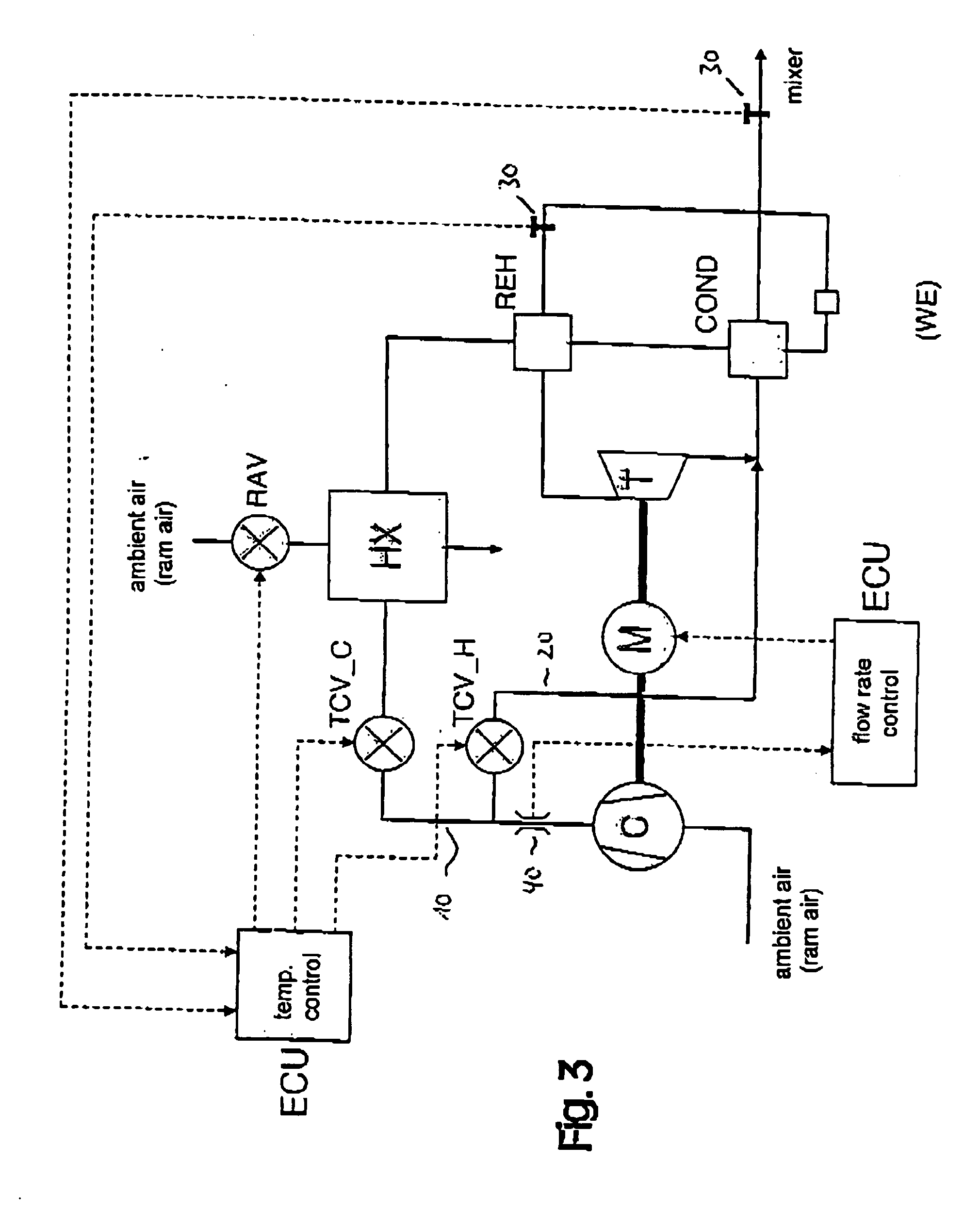
[0038]FIG. 3 shows the aircraft air conditioning system in accordance with the invention in a first schematic representation. On the inlet side, the compressor C is supplied with ambient or ram air or for instance also with precompressed air. On the pressure side of the compressor, the first conduit 10 is provided, from which branches a bypass conduit 20.

[0039] Subsequent to this branching, the first conduit 10 includes a throttle means TCV_C, by means of which the mass flow through the first conduit can be varied. Downstream of this throttle means, the ram-air heat exchanger HX is provided, which is traversed by ram or ambient air and on its warm side is traversed by the compressor outlet air, which undergoes cooling in the heat exchanger HX.

[0040] The mass flow of the ambient or ram air is varied by means of the valve RAV provided on the ram air side, as is indicated in FIG. 3.

[0041] The compressed air cooled in the ram-air heat exchanger HX then flows into the reheater REH and...


PUM


Abstract

The invention relates to an aircraft air conditioning system with at least one compressor, comprising a first conduit which is connected with the pressure side of the compressor and in which one or more cooling means provided downstream of the compressor are arranged for cooling the air compressed in the compressor, and comprising a second conduit designed as bypass conduit, which likewise is connected with the pressure side of the compressor and is arranged such that it conducts at least part of the air compressed in the compressor in a bypass around at least one of the cooling means, wherein a throttle means is arranged in the bypass conduit, by means of which the mass flow of the air conducted through the bypass conduit can be varied, and that a unit (ECU) is provided, which is designed such that it can be operated in a first and / or in a second operating mode, wherein in the first operating mode, when the opening of the throttle means (TCV_H) provided in the bypass conduit (20) is increased, the unit (ECU) effects a reduction of the opening of the throttle means (TCV_C) provided in the first conduit (10), and, inversely, when the opening of the throttle means (TCV_H) provided in the bypass conduit (20) is reduced, effects an increase of the opening of the throttle means (TCV_C) provided in the first conduit (10), and in the second operating mode effects an increase of the opening of the throttle means (TCV_H) provided in the bypass conduit (20) and of the throttle means (TCV_C) provided in the first conduit (10) or a reduction of the opening of the throttle means (TCV_H) provided in the bypass conduit (20) and of the throttle means (TCV_C) provided in the first conduit (10). The invention furthermore relates to a method of operating an aircraft air conditioning system.

Description

BACKGROUND OF THE INVENTION [0001] This invention relates to an aircraft air conditioning system with at least one compressor, comprising a first conduit which is connected with the pressure side of the compressor and in which one or more cooling means provided downstream of the compressor are arranged for cooling the air compressed in the compressor, and comprising a second conduit designed as bypass conduit, which likewise is connected with the pressure side of the compressor and is arranged such that it conducts at least part of the air compressed in the compressor in a bypass around at least one of the cooling means, wherein a throttle means is arranged in the bypass conduit, by means of which the mass flow of the air conducted through the bypass conduit can be varied. [0002] Aircraft air conditioning systems, which include compressors supplied with ambient air or precompressed air, are known in a number of different embodiments. A problem of electrically driven aircraft air con...

Claims


Application Information

Patent Timeline
Patent Type & Authority Applications(United States)
IPC IPC(8): B64D13/06
CPCB64D13/06Y02T50/56B64D2013/0648B64D2013/064Y02T50/50
Inventor VOGEL, FRANZ MARTIN
Owner LIEBHERR AEROSPACE LINDENBERG
Learn More