
Locking System And Flooring Board

a technology of locking system and flooring board, which is applied in the direction of load-supporting elements, structural elements, building components, etc., can solve the problems of high friction and difficulty in angling together and displacing the boards, different joint designs affecting the costs to a considerable extent, and the cost of waste is different, so as to achieve low friction, high guiding capability, and low cost

Inactive Publication Date: 2008-02-07
VÄLINGE INNOVATION AB
View PDF99 Cites 356 Cited by
  • Summary
  • Abstract
  • Description
  • Claims
  • Application Information

AI Technical Summary

Benefits of technology

[0040] The above problem of undesirable costs of material is solved according to the invention by the projecting portion being made of different materials and / or material combinations and thus specially adaptable to the selected materials in the floorboard and the function and strength requirements that apply to the specific floorboard and that are specific for long side and short side. This advantage of the invention will be evident from the following description.
[0041] Since different requirements are placed on the long side and the short side and also the cost of waste differs, improvements can also be achieved by the long side and the short side being made of different materials or combinations of materials. In some applications, the long side can have, for instance, an aluminum strip with high guiding capability and low friction whereas the short side can have a wood fiber strip. In other applications, the opposite is advantageous.
[0042] In some applications, there may also be a need for different types of strip on the same side. The side may consist of, for instance, a plurality of different strips which are made of different aluminum alloys, have different thicknesses etc. and in which certain parts are intended to achieve high strength and others are intended to be used for guiding.
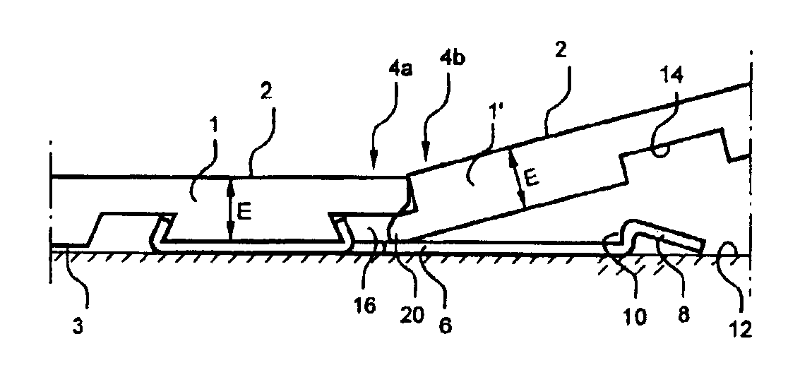
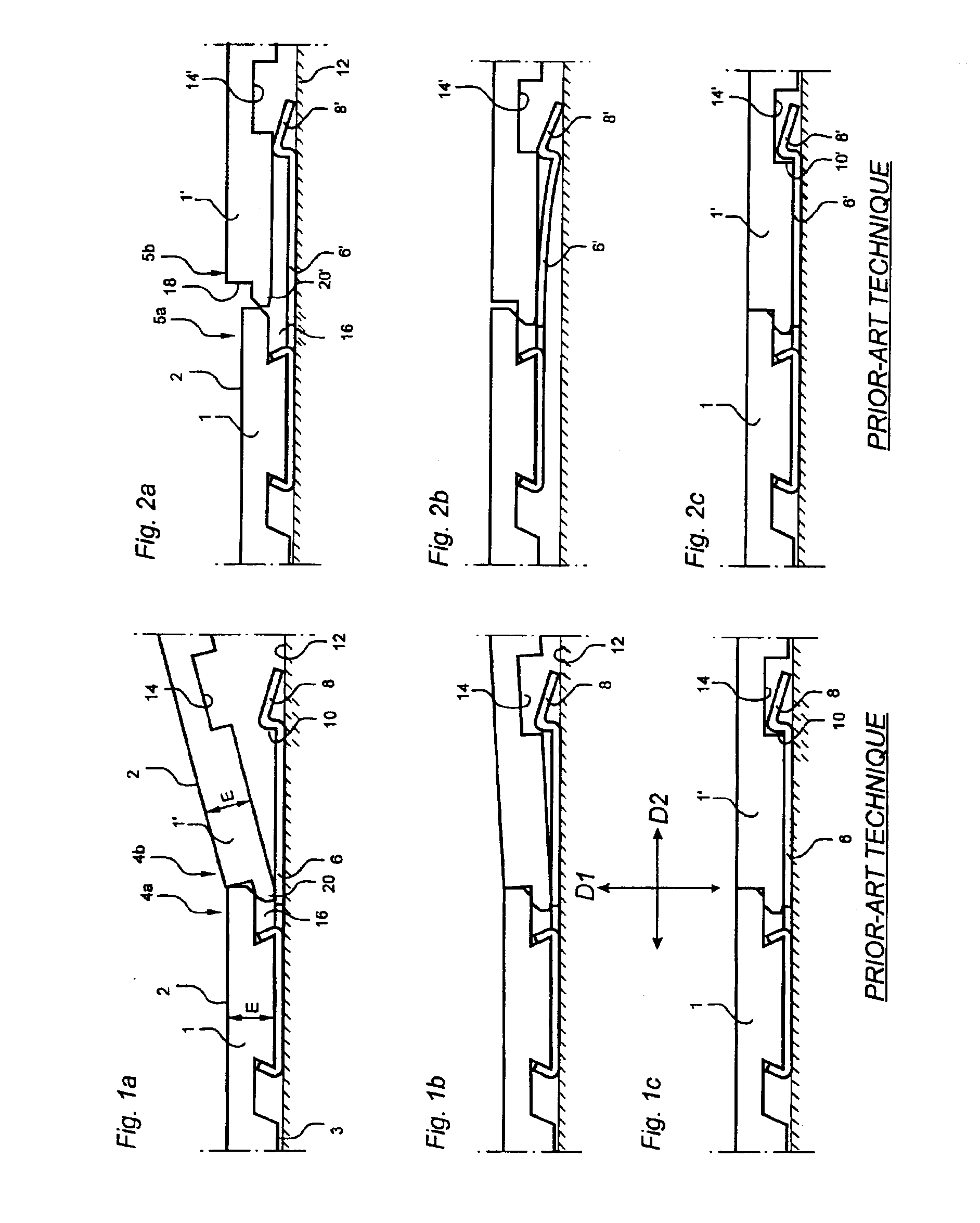
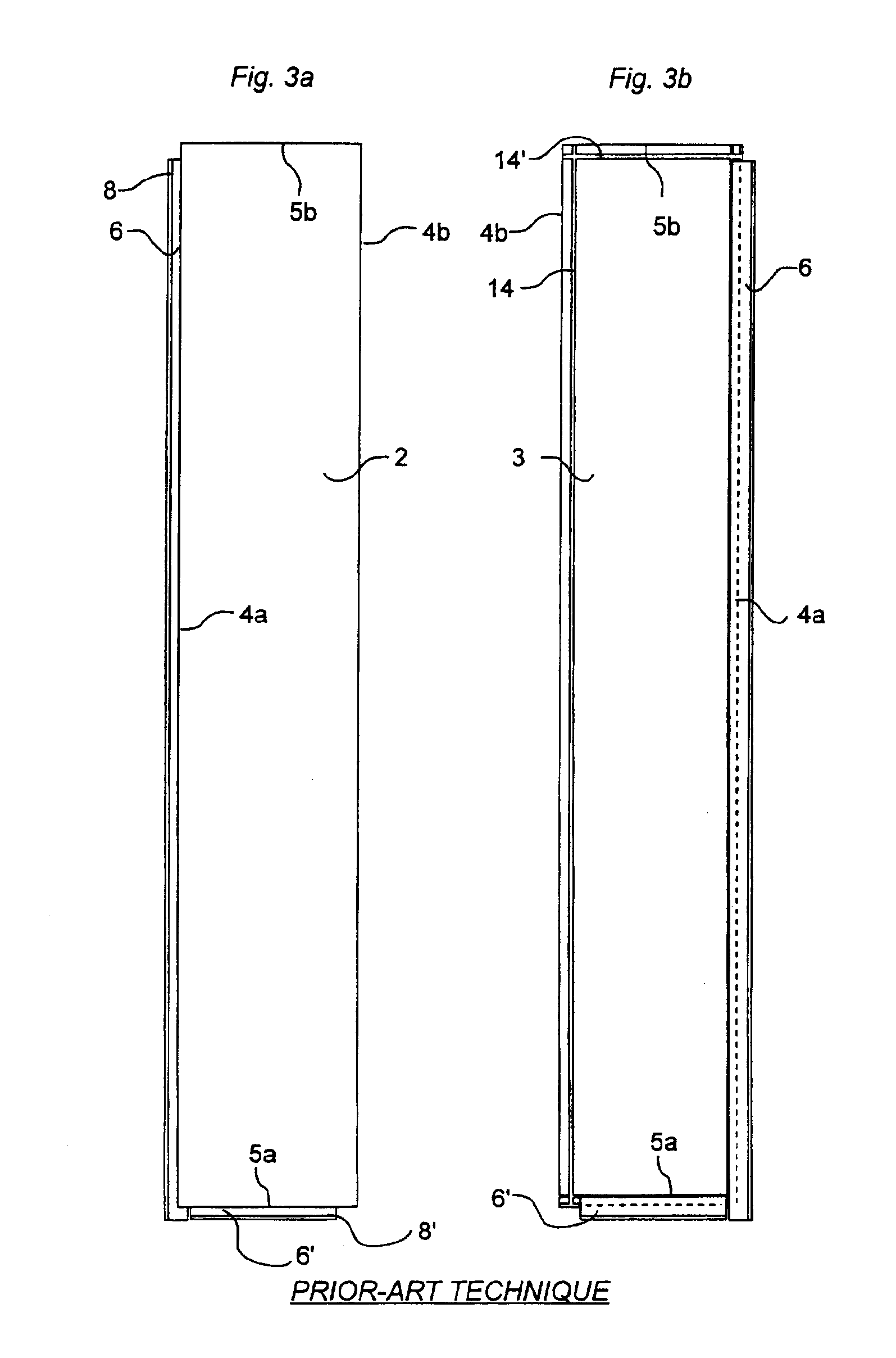
[0043] Different aspects of the invention will now be described in more detail by way of examples with reference to the accompanying drawings. The parts of the inventive board which are equivalent to those of the prior-art board in. FIGS. 1-3 are provided with the same reference numerals.

Problems solved by technology

This leads to high friction and difficulties in angling together and displacing the boards.
This solution involving an integrated strip, however, leads to costs in the form of waste when the mechanical joint is being made.
Different joint designs affect the costs to a considerable extent.
If the same strength is to be achieved with a locking element of wood fiber, it must be wide with a large shearing surface, which results in a large amount of waste material in manufacture, or it must be reinforced with a binder.
Depending on the size of the boards, working of, for instance, 10 mm of a joint edge may result in six times higher cost of waste per m2 of floor surface along the long sides compared with the short sides.
It is not possible to achieve a low cost with prior-art solutions without also lowering the requirements as to strength and / or laying function.

Method used


Image

  • Locking System And Flooring Board
  • Locking System And Flooring Board
  • Locking System And Flooring Board

Examples


second embodiment

[0064]FIG. 8 shows the invention. The board 1 in FIG. 8 can be used for parquet flooring. The board 1 consists of an upper wear layer 32a, a core 30 and a rear balance layer 34a. In this embodiment, the projecting portion P outside the joint plane F is to a still greater extent made of different combinations of materials. The locking groove 14 is reinforced by the use of a separate component 70 of, for instance, wood fiber, which in a suitable manner is connected with the joint edge, for instance by gluing. This variant can be used, for instance, on the short side 5b of the board 1. Moreover, a large part of the fixing shoulder 60 is positioned outside the joint F.

third embodiment

[0065]FIG. 9 shows the invention. The board 1 in FIG. 9 is usable to provide a strong attachment of the aluminum strip 6. In this embodiment, a separate part 72 is arranged on the joint edge supporting the locking element 8. The part 72 can be made of, for instance, wood fiber. The entire fixing shoulder 60 and the entire strip 6 are located outside the joint plane F. Only a small part of the separate strip 6 is used for resilience. From the viewpoint of material, the portion P located outside the joint plane F has three different areas containing the combinations of materials “wood fiber only” (P1), “wood fiber / balance layer / aluminum” (P2) and “aluminum only” (P3). This embodiment with the fixing shoulder 6 positioned entirely outside the joint plane F can also be accomplished merely by working the body of the board, i.e. without the separate part 72. The embodiment in FIG. 9 can be suitable for the long side. The locking element 8 has a large guiding part, and the projecting porti...


PUM


Abstract

A locking system for mechanical joining of floorboards, each of the floorboards comprising a body comprising plywood with several layers; a locking groove which is formed in an underside of and extends in parallel with a first joint edge at a distance from the joint plane, the locking groove having an opening, a bottom, and two side walls; a portion projecting from a lower part of the second joint edge and below the first joint edge and integrated with the body of the board; said projecting portion supporting, at a distance from the joint plane, a locking element for cooperating with the locking groove; said projecting portion being located entirely outside the joint plane as seen from the side of the second joint edge; and the walls of the locking groove comprise at least two layers of the body.

Description

CROSS-REFERENCE TO RELATED APPLICATIONS [0001] The present application is a continuation of Ser. No. 10 / 906,109, filed on Feb. 3, 2005, and which is a continuation-in-part of Ser. No. 10 / 361,815, which is a continuation of Ser. No. 10 / 100,032, which is a continuation of Ser. No. 09 / 679,300, which is a continuation of PCT / SE99 / 00934. The entire contents of Ser. No. 10 / 361,815, Ser. No. 10 / 100,032, Ser. No. 09 / 679,300, and PCT / SE99 / 00934 are incorporated herein by reference. [0002] The invention generally relates to a locking system for providing mechanical joining of floorboards. More specifically, the invention concerns an improvement of a locking system of the type described and shown in WO 94 / 26999. The invention also relates to a floorboard provided with such a locking system. According to one more aspect of the invention, a floorboard with different designs of the locking system on long side and short side is provided.FIELD OF THE INVENTION [0003] The invention is particularly s...

Claims


Application Information

Patent Timeline
Patent Type & Authority Applications(United States)
IPC IPC(8): E04F13/08E04F15/04
CPCE04F15/02E04F15/04E04F2201/0115E04F2201/0517E04F2201/026E04F2201/041E04F2201/045E04F2201/0153
Inventor PERVAN, DARKO
Owner VÄLINGE INNOVATION AB
Learn More